
Specifications


14
CONTENTS
The drain line flow control can be installed in the standard
1/4" drain line elbow, which accommodates 5/8" poly tube or
3/4" NPT drain line connections. The optional nut and poly
tube insert for the 3/4" drain line elbow is designed for use
with flexible poly tube only. The 3/4" drain line elbow can be
rotated 180 degrees so the outlet can be orientated to the
nearest drain. The same retainer is used for all drain line flow
controls for the 3/4" fitting.
Water Meter or Meter Plug
The water meter is installed on the outlet side of the control
valve. The water meter uses a turbine to total gallons of treat-
ed water. The turbine rotates with the flow of water and
reports its rate of rotation through Hall-effect 8 circuitry to the
printed circuit (PC) board. This rotation permits the PC board
to record the total volume of treated water and the flow rate.
The small centrally located magnet is shielded from water,
which reduces substantially iron-fouling problems with the
turbine. The turbine is accurate to within ± 5% over a wide
operating flow rate range (0.25 gpm up to control valve max-
imums) and has a very low pressure drop. Water used for
regeneration is not metered. If the control valve is set to pre-
fill the regenerant, water used between the prefill cycle up to
the start of the regeneration cycle is metered. If the control
valve is in regeneration mode (e.g. a backwash cycle) and
there is a water demand that water usage is not metered.
When facing the front of the control valve, the water meter is
positioned on the left-hand side of the control valve. Allow
sufficient clearance to clean and repair the water meter with
out disconnecting the plumbing or disassembling any other
parts of the control valve.
A unique feature of this control valve is the ability to display
actual water usage for the last 63 days. The values are initially
stored as "_" because it is is unknown. As days pass values
are stored as “O” for no flow or the actual number of galons.
The counting of the gallons starts at the regeneration
time. If no regeneration time can be set (i.e. when the valve is
set for immediate regeneration) the counting, of gallons starts
at 12 a.m. Day 1 is yesterday, day 2 the day before yesterday,
etc. As new values are added the oldest history disappears.
Another unique feature is that the valve automatically calcu-
lates a reserve capacity when set up as a softener with
“Gallons Capacity” set to “AUTO”. The reserve capacity for a
given day of the week is the middle value stored for the last
three non-trivial water usages (i.e. less than 20 gallons day)
in seven-day intervals which is then adjusted either upward or
downward depending upon the difference between today’s
water usage and the estimated reserve capacity.
Installation Fitting Assemblies
The installation fittings are used to connect the optional
bypass or the control to the plumbing system. There are four
installation-fitting assemblies available:
1. 1" NPT elbow
2. 3/4" & 1" PVC solvent weld elbow fitting
3. 1" straight brass sweat fitting **
4. 3/4" straight brass sweat Fitting **
Both elbow fittings have a unique drill out feature to allow a
1/4" NPT connection to the inlet and/or outlet which can be
used for a RO feed, test ports, pressure tap ports, etc.
The installation fitting assemblies are sold in pairs and
consist of two fittings, two nuts, two split rings and two o-
rings. The installation fitting assemblies and the bypass valve
are sold separately from the control valve.
Bypass Valve
The bypass valve is typically used to isolate the control valve
from the plumbing system’s water pressure in order to per-
form control valve repairs or maintenance. The W100SM
bypass valve is particularly unique in the water treatment
industry due to its versatility and state of the art design
features. The 1" full flow bypass valve incorporates four posi-
tions including a diagnostic position that allows service per-
sonal to work on a pressurized system while still providing
untreated bypass water to the facility or residence. Its
completely non-metallic, all plastic design allows for easy
access and serviceability without the need for tools.
The bypass body and rotors are glass filled Noryl and the
nuts and caps are glass filled polypropylene. All seals are
self-lubricating EPDM to help prevent valve seizing after long
periods of nonuse. Internal o-rings can easily be replaced if
service is required.
The bypass consists of two interchangeable plug valves that
are operated independently by red arrow shaped handles.
The handles identify the flow direction of the water. The plug
valves enable the bypass valve to operate in four positions.
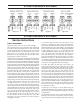
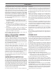
1. Normal Operation Position: The inlet and outlet handles
point in the direction of flow indicated by the engraved
arrows on the control valve. Water flows through the
control valve during normal operation and this position
also allows the control valve to isolate the media bed
during the regeneration cycle. (See Figure 17)
2. Bypass Position: The inlet and outlet handles point to the
center of the bypass, the control valve is isolated from the
water pressure contained in the plumbing system.
Untreated water is supplied to the plumbing system.
(See Figure 18)
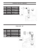
3. Diagnostic Position: The inlet handle points in the direction
of flow and the outlet handle points to the center of bypass
valve, system water pressure is allowed to the control
valve and the plumbing system while not allowing w ater
to exit from the control valve to the plumbing.
(See Figure 19)
4. Shut Off Position: The inlet handle points to the center of
the bypass valve and the outlet handle points in the
direction of flow, the water is shut off to the plumbing
systems. If water is available on the outlet side of the
softener it is an indication of water bypass around the
system (i.e. a plumbing connection somewhere in the
building bypasses the system). (See Figure 20)
* Some semiconductor materials exhibit a phenomenon in the presence of a magnetic
field that is adaptable to sensing devices. When a current is passed through one pair of
wires attached to a semiconductor, another pair of wires properly attached and orient-
ed with respect to the semiconductor will develop a voltage proportional to the magnet-
ic field present and the current in the other pair of wires. Holding the exiting current
constant and moving a permanent magnet near the semiconductor produces a voltage
output proportional to the movement of the magnet. Hall-effect devices provide a
high-speed response, excellent temperature stability and no physical contact.
** Has not been tested for compliance with California Proposition 65 so this
fitting should not be installed in California.