
Specifications


15
SYSTEM COMPONENTS DESCRIBED
SYSTEM COMPONENTS DESCRIBED
DRIVE ASSEMBLY
Remove the valve cover to access the drive assembly.
Disconnect the power source plug (black wire) from the PC
board prior to disconnecting the motor or water meter plugs
from the PC board. The motor plug connects to the two-pin
jack on the left-hand side of the PC board. The power source
plug connects to the four-pin jack. The four-pin jack is
between the two-pin and three-pin jacks. The water meter
plug (gray wire) connects to the three.
The PC board can be removed separately from the drive brack-
et but it is not recommended. Do not attempt to remove the dis-
play panel from the PC board. Handle the board by the edges.
To remove the PC board from the drive bracket, unplug the
power, water meter and motor plugs from the PC board. Lift the
middle latch along the top of the drive bracket while pulling out-
ward on the top of the PC board. The drive bracket has two
plastic pins that fit into the holes on the lower edge of the PC
board. Once the PC board is tilted about 45˚ from the drive
bracket it can be lifted off of these pins. To reinstall the PC
board, position the lower edge of the PC board so that the
holes in the PC board line up with the plastic pins. Push the top
of the PC board towards the valve until it snaps under the
middle latch, weave the power and water meter wires into the
holders and reconnect the motor water meter and power plugs.
The drive bracket must be removed to access the drive cap
assembly and pistons or the drive gear cover. It is not
necessary to remove the PC board from the drive bracket to
remove the drive bracket. To remove the drive bracket start by
removing the plugs for the power source and the water meter.
Unweave the wires from the side holders. Two tabs on the
top of the drive back plate hold the drive bracket in place.
Simultaneously lift the two tabs and gently ease the top of
the drive bracket towards your body. The lower edge of
the drive bracket has two notches that rest on the drive
back plate. Lift up and outward on the drive bracket to
disengage the notches.
To reassemble seat the bottom of the drive bracket so the
notches are engaged at the bottom of the drive back plate.
Push the top of the drive bracket towards the two latches.The
drive bracket may have to be lifted slightly to let the threaded
piston rod pass through the hole in the drive bracket. Maintain
a slight engaging force on top of the drive bracket while
deflecting the bracket slightly to the left by pressing on the
side of the upper right corner. This helps the drive gears
mesh with the drive cap assembly. The drive bracket is
properly seated when it snaps under the latches on the drive
back plate. If resistance is felt before latching, then notches
are not fully engaged, the piston rod is not in hole, the wires
are jammed between the drive bracket and drive back plate,
or the gear is not engaging the drive cap assembly.
To inspect drive gears, the drive gear cover needs to be
removed. The drive gear cover is held in place on the drive
bracket by three clips. The largest of the three clips is always
orientated to the bottom of the drive bracket. Before trying to
remove the drive gear cover, the drive bracket must be
removed from the drive back plate. The drive gear cover can
be removed from the drive bracket without removing the
motor or the PC board. Simultaneously, push in and down on
the large clip at the bottom and the clip on the left-hand side
of the drive bracket behind the PC board. Keep your other
fingers behind the drive gear cover so the drive gears do not
drop on the ground. Replace broken or damaged drive gears.
Do not lubricate any of the gears. Avoid getting any foreign
matter on the reflective coating because dirt or oils may inter-
fere with pulse counting.
The drive gear cover only fits on one way, with the large clip
orientated towards the bottom. If all three clips are outside of
the gear shroud on the drive bracket the drive gear cover slips
easily into place.
The drive bracket does not need to be removed from the drive
plate if the motor needs to be removed. To remove the motor,
disconnect the power and motor plugs from the jacks on the PC
Service Instructions
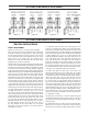
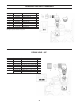
Figure 17: Figure 18: Figure 19 Figure 20::