
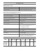
Specifications


INSTALLATION
Conduct a visual check of all equipment for any damage that
may have occurred during shipment.
Note: If there is obvious damage to any equipment, it should
be noted on the carrier’s Bill Of Lading. Open and inspect the
contents of all closed crates, cartons, etc. and inspect for con-
cealed damage. The manufacturer is not liable for any dam-
age during transit.
Position the equipment in its proper location, setting on a flat
surface. Level equipment as required. Equipment out of
plumb can exhibit poor flow characteristics, which will affect
the performance of the system.
Note: Units are shipped with media (resin & gravel), distribu-
tions tube, and control valve installed. Double-check the valve
installation on the tank. Tighten if necessary.
Unit should be positioned with the valve control facing forward.
Check the main line water pressure. The softener is designed
for a minimum of 20 psi and a maximum of 125 psi working
pressure. If the line pressure exceeds this limit, a pressure-
reducing valve should be installed.
Maximum allowable water temperature is 40°F (4°C) – 110°F
(38°C). A 120vac 60 cycle electrical source must be available
for operation of the controller.
Connect raw water supply line to the inlet valve connection.
Connect treated water outlet to service line. It is suggested that the
pipe size be equal or one size larger than the valve connection.
Note: Softener to be located at least 10 feet away from hot
waterheater to protect against hot water back-up.
Warning: When piping with copper, solder all piping as sub-
assemblies before installing. Internal damage can result from
the high heat of the torch.
It is recommended that manual isolating valves be installed
on the inlet and outlet piping along with a system bypass
valve. This will isolate the unit when service is required.
Run drain line to a sump, drain trench, or other open drain.
Open drains are required for taking samples and allowing a
visual check. Avoid overhead pipe runs to drain facility, as
undue backpressure will affect the operation of injectors.
Note: All piping is to meet your local and state code. AVOID
CROSS CONNECTIONS!
Position brine tank approximately 6" from the softener tank on
a smooth surface.
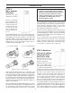
Connect the brine air check assembly in the salt/brine tank to
the brine suction (eductor) connection. If brine tank is located
more than 6 feet from softener tank, use one size larger tub-
ing. Tubing 5/8" should be installed from the brine tank over-
flow to drain. This is a gravity drain designed to divert brine to
the drain in the event of a malfunction, which would cause
overflow of the brine tank.
Be sure inlet/outlet isolating valves are closed and bypass
valve is open.
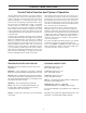
Installation Preview
STEP 1: Select Location
Locate main water supply for all faucets and appliances in
home (if possible outside faucets should be separate so not
to waste soft water).
Select location that is easily accessible to 110vac power. A
15-foot power cord is provided.
You will also need a drain close by for disposal of regenerat-
ed wastewater.
Leave enough room between walls so you can easily add salt
when needed.
Locate the water softener at least 10 feet away from the hot
water heater so that hot water does not backup and damage
the softener.
Make sure water softener is in a level spot. You may be
required to put the softener on a platform, such as a piece of
3/4” plywood and shimmed to become level.
Make sure softener is behind any other water conditioning
systems installed in series, except a system that is for taste
and odor or a Reverse Osmosis system.
Select a location were water damage will be least likely to
occur if a leak should develop.
If installing the softener in an outside location make sure
to protect from the elements, such as rain, sunlight, and
contamination.
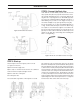
STEP 2: Install a bypass
Note: Always install a bypass, either a 3-way valve system
or the standard bypass for the valve you have. This will allow
you to shut off the water supply to the softener, but still have
water in the house if the softener is in need of repair.
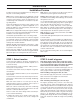
After a location has been determine install bypass onto the
control valve. (Figures 1 and 3 show standard bypass on
valve.) (Figures 2 and 4 show 3-way by pass plumbing.)
Note: If installing a 3-way bypass valve, do so now.
Close main water supply valve, at the well or at the water meter.
Shut off electrical or fuel supply to the water heater.
Open all faucets to drain pipes.
Note: If installing standard bypass, move to step 3.
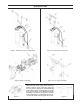
The bypass (provided) easily connects to the valve body
using nuts that only require hand tightening. The split ring
retainer design holds the nut on and allows load to be spread
over the entire nut surface area reducing the chance for leak-
age. Make certain the nut is placed on first, then the split
retainer ring, followed by the o-ring to make the seal. A silicon
lubricant may be used on the black o-ring seals. This design
allows for an approximate 2-degree misalignment of the
plumbing. This design will allow for minor plumbing misalign-
ments, but should never handle the weight of the plumbing
system.
Installation
6