
Underfloor Mat Submittal

PRODUCT INSTALLATION
Examination
Installer must
•verifythattheareabelowthesubfloorisclearandclean
of sharp objects such as nails from above, and is ready to
receive work.
•verifyfieldmeasurementsareasshownondrawings.
•verify mats and control are correct size and voltage for area.
•verifythatrequiredutilitiesareavailable,inproper
locations, and ready for use.
•using a digital ohm meter, verify the cable resistance with the
manufacturers values printed on the UL tag.
Beginning of installation signifies that installer accepts
conditions.
UnderFloor Mat Installation
Follow the detailed instructions in the Heatweave UnderFloor
Installation Manual. In brief, these are:
Use a digital ohmmeter to measure and certify the correct wire
resistance (ohm) value for the mat. Check this resistance value
regularly during and after the installation. Record these readings
in the chart provided in the installation manual.
Use of manufacturer’s LoudMouth
™
monitor is recommended
for continuous monitoring of the mat during installation. The
LoudMouth shall monitor ground, line, and neutral wires of the
mat, and shall sound an alarm if there is a break in the circuit or
a short to ground. LoudMouth shall have integral test button/light
to verify proper battery power.
Install the floor sensor in the heated floor area, according to
installation manual. This can be done in the floor surface above
or in the subfloor below.
Completely unroll the mat to make sure it fits between joists
and obstructions. Use finish staples to secure the mesh edging to
the joists, 2" below the subfloor.
CAUTION: Never allow nails or staples to touch the heating
elements. Never use metallic fasteners to secure the blue
heating elements. Metal fasteners may damage the heating
elements.
Mount a junction box(es) below the floor to receive the
UnderFloor mat power leads and power wiring to the control.
Insulate with R-11 to R-19 fiberglass batt below the mats and in
adjacent joist areas.
Do not cut, damage, or staple the heating elements. Do not
cut the mats to make them shorter. Do not overlap the mat on
itself or install one mat over another. Do not roll or bunch the
mat to fit. Do not install the mat closer than 2" from the subfloor.
Remember to measure and record mat resistance readings. Use
licensed electrical installers and follow all building and electrical
codes.
Control Installation
Test the supply to ensure voltage at each unit and verify the
correct voltage is available, as per UL Listing label attached to
heating mat.
Properly choose correct SunStat control(s) and protection devic-
es for the heating area. A SunStat can control up to about 190
sq.ft. at 120 VAC (15 amps), and about 350 sq.ft. at 240 VAC
(15 amps). If amperage draw is greater than this for one zone,
SunStat Relay(s) are required for safe mat operation.
Install all controls according to all applicable local and national
codes, and to manufacturer’s guidelines.
Copyright © 2008 Watts Radiant, Inc. Heatweave Underfloor®
Submittal LIT#HWUFSUB0908 Effective 10/15/2008
The Heatweave name, the sunrise logo are registered trademarks of Watts Radiant, Inc.
Heatweave UnderFloor Mat Sizes
Control Options
Qty. Model No. Volts Description
500670 120/240 SunStat Pro
(digital programmable)
500675 120/240 SunStat (digital non-programmable)
500710 120/240 SunStat Dial (non-programmable)
500680 120/240 SunStat Relay
423250 NA LoudMouth Monitor
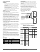
Typical Electrical Wiring Diagram with
SunStat Controller (120V or 240V)
All electrical work must be done by a qualified, licensed electrician in accordance with local build-
ing and electrical codes, and the National Electrical Code (NEC), especially Article 424, Part IX of
the NEC, ANSI/NFPA 70 and Section 62 of CEC Part I.
Ground
Black
Black
Black
White
White
White
Line 1
Load 1
Load 2
Line 2
120 VA C or 240 V A C
Sensor Wire
(no polarity)
UnderFloor Mat
(maximum 15 amps)
120/240 VA C
SunStat Control
Tw o or more120 VA C or
240 VA C Heating Mats
(maximum 15 amps)
CAUTION: Make sure 120 VA C
is supplied to 120VAC mats and
240VAC is supplied to 240VAC
mats. Otherwise, dangerous
overheating and possible fire
hazard can result.
CAUTION: Make sure 120 VA C
is supplied to 120VAC mats and
240VAC is supplied to 240VAC
mats. Otherwise, dangerous
overheating and possible fire
hazard can result.
Ground
Black
Black
Black
White
White
White
Line 1
Load 1
Load 2
Line 2
120 VA C or 240 V AC
Sensor Wire
(no polarity)
120/240 VA C
SunStat Control
old one
Connecting two mats
Amp Resistance
Mat Size Draw (ohms)
12" x 5.5' 0.4 247–302
12" x 8' 0.6 167–204
12" x 10.5' 0.9 121 –148
12" x 13' 1.1 97–119
12" x 16' 1.3 80–98
12" x 19' 1.5 67–82
16" x 4' 0.4 258–315
16" x 6' 0.6 173–211
16" x 8' 0.8 126–154
16" x 9.5' 1.0 101–123
16" x 12' 1.3 82–101
16" x 14' 1.5 69–85
16" x 16' 1.7 63–78
16" x 18' 1.9 53–65
16" x 19.5' 2.1 45–56
19.2" x 4.5' 0.7 170–207
19.2" x 6.5' 0.9 127–155
19.2" x 8' 1.0 103–126
19.2" x 9.5' 1.3 83–102
19.2" x 11.5' 1.5 71–87
19.2" x 13' 1.7 63–78
19.2" x 14.5' 1.8 54–66
19.2" x 16' 2.1 45–56
Amp Resistance
Mat Size Draw (ohms)
12" x 10.5' 0.4 500–611
12" x 16' 0.6 336–411
16" x 8' 0.4 521–636
16" x 12' 0.6 362–443
16" x 16' 0.8 253 –310
16" x 19.5' 1.0 207–253
19.2" x 6.5' 0.4 526–643
19.2" x 9.5' 0.6 359–439
19.2" x 13' 0.9 256–313
19.2" x 16' 1.0 207–253
19.2" x 19' 1.3 167–204
120 VAC
240 VAC
UnderFloor Mat
UnderFloor Mat