
Installation Manual
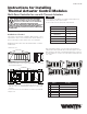

Zone 1 LED
2.5A Fuse
Pump
Relay
+ -
Zone 2 LED Zone 3 LED Zone 4 LED Zone 5 LED Zone 6 LED
IS-WR-Control-TAC
Instructions for Installing
Thermal Actuator Control Modules
Multi-Zone Controller for use with Thermal Actuators
Read these instructions and all product labels BEFORE
installation. Installation must be performed by qualified
personnel, in accordance with local codes and standards.
FAILURE TO COMPLY WITH PROPER INSTALLATION
INSTRUCTIONS COULD DAMAGE PIPING, CONNECTIONS, AND ELECTRICAL
ELEMENTS WHICH MAY CAUSE WATER DAMAGE AND/OR DAMAGE TO
THE PIPING SYSTEM WHICH CAN RESULT IN PROPERTY DAMAGE AND/OR
PERSONAL INJURY
WARNING
NOTICE
Thermal Actuator Control Modules are not water resistant. Install in a dry
location away from possible exposure to water.
Do not exceed the electrical capacity of the module terminals..
When using expansion modules, secure the module to the DIN rail before
sliding the two modules together. Modules should sit flush against each other.
When mounting to a flat surface, install the Master Module first, securing it to
the surface with the use of screws. Connect the expansion module and screw
to the surface.
√ Order # Description
81005192 Master, 4 Zone Control
81005190 Master, 6 Zone Control
81009509 60 VA Transformer
81005246 Slave, 4 Zone Control Extension
81005191 Slave, 6 Zone Control Extension
Cover Screws
Screw Mounts
Item Feature/Capacity
Max VA/Terminal Block 7.5 VA
Max Amp/Terminal Block 0.3 A
Max Number of Actuators/
Terminal Block
3
Max Number of Actuators 18
4 Zone Size 6-3/4” x 3-1/2”
6 Zone Size 8-3/4” x 3-1/2”
Zone 1 LED
2.5A Fuse
Pump
Relay
+ -
Zone 2 LED Zone 3 LED Zone 4 LED Zone 5 LED Zone 6 LED
Zone 1 LED
2.5A Fuse
Pump
Relay
+ -
Zone 2 LED Zone 3 LED Zone 4 LED Zone 5 LED Zone 6 LED
Zone 1 LED
2.5A Fuse
Pump
Relay
+ -
Zone 2 LED Zone 3 LED Zone 4 LED Zone 5 LED Zone 6 LED
Zone 1 LED
2.5A Fuse
Pump
Relay
+ -
Zone 2 LED Zone 3 LED Zone 4 LED Zone 5 LED Zone 6 LED
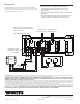
Installation of Control
Control modules come in two main configurations, Master and Slave. Connect
a Slave module to either a 4 our 6 zone Master if more than the allotted 4 or 6
zones are required. No more than 3 modules can be connected together.
Both Master and Slave modules can be either DIN rail mounted or screwed to
a suitable backer.
1. Remove the cover.
2. Mount control
Directly to a flat surface: Secure control to surface with 1/4" screws through
the provided mounting holes.
Directly to DIN Rail: Tilt control so the DIN Rail slides into the top slot on the
back of the control. Press downward until the bottom of the control "clicks"
in to place.
3. Connect all electrical connections. Maximum of 3 actuators per thermostat.
4. Replace cover.