
Install Instructions

Period Inspection/Maintenance
This valve requires periodic inspection and verification of the out-
let temperature by a licensed contractor. Corrosive water condi-
tions, hot inlet water temperature over 200°F (93°C), unauthor-
ized adjustments or repairs could render the valve ineffective for
its intended service. Regular cleaning and checking of thermo-
stat assembly helps to maximize valve life and Tempering func-
tion. Frequency of cleaning depends on local water conditions.
NOTE: It is recommended that shutoff valve(s) be installed on
the inlet(s) to facilitate service of the MMV-M1 or LFMMV-M1
valve.
Pressure –– Temperature –– Flow Rate
Minimum Supply Pressure Static: 30psi (207 kPa)
Inlet Temperatures: hot inlet, 120°F – 180°F (49°C – 82°C),
cold inlet, 39°F – 85°F (4°C – 29°C)
Hot Water Inlet to Outlet Differential Temperature: 5°F (3°C)
Temperature Out: Field range: 80°F – 120°F (27°C – 49°C),
adjustable; Accurate within ±3°F (1.7°C)
Maximum Temperature: 200°F (93°C)
Maximum Pressure: 150psi (1034 kPa)
Minimum Flow: 0.5 gpm (1.9 lpm) @.08psi (0.55 kPa)
†
Maximum Flow: 20 gpm (76 lpm) @ 125psi (862 kPa)
†
Maximum Pressure Differential between
Hot & Cold Water Supplies: 25%
Listing: ASSE 1017, ASSE 1069, ASSE 1070 and IAPMO cUPC
†
When tested in accordance with ASSE 1017, ASSE 1069, ASSE 1070
and IAPMO cUPC.
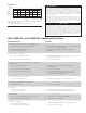
Figure 4
Temperature Adjustment
1. Let the water flow for at least two minutes to allow supply
temperature to stabilize.
2. Calibrate the mixed water outlet temperature by placing a
thermometer in the mixed water stream.
3. To adjust the setting of the valve, loosen locking cap screw
with hex wrench, see Figure 4. Cap must be lifted
1
/4" to
adjust temperature. To increase the temperature, turn coun-
terclockwise. To decrease temperature turn clockwise.
4. Lower handle and tighten screw.
5. Check outlet temperature.
Factory Preset: MMV-M1, LFMMV-M1: 105°F (41°C)
Under following conditions:
Cold Inlet: 60-70°F (16-21°C)
Hot Inlet: 140-145°F (60-63°C) Supply Pressure: 45psi (310 kPa)
Hot
140°F
Cold
Cold
Hot
MMV-M1 or
LFMMV-M1
Mixed
110°F
Mixed
110°F
Hot
Cold
Cold
Supply
Stops
Typical
Two Handled Faucet
Typical
Two Handled Faucet
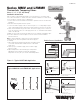
Figure 2 – Typical ASSE 1070 Application
† Devices tested to ASSE 1069 or ASSE 1070 such as Watts
Series USG, LFUSG, L111, MMV or LFMMV should be used at
fixture to prevent possible injury.
Watts
Vacuum Relief
Valve
Watts
Temperature
Gauge
Cold
Cold
Cold
MMV-M1 or
LFMMV-M1
Tempered †
Hot
Hot to
Appliances
Watts T&P
Relief Valve
*8" – 12"
H
C
M
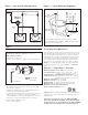
Figure 3 – Typical ASSE 1017 Application
Hotter
3
/32" Hex Wrench
Turn
Colder
Unscrew, lift
cap to adjust
*Important: To prolong the life of the series MMV and LFMMV
when used in an ASSE 1017 application, it is recommended that it
be trapped as shown; i.e. the hot water inlet to the MMV or LFMMV
should be 8"-12" (200-305mm) below the hot water supply feed.