
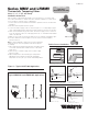
Install Instructions
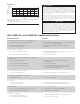

Flow curves are for reference. Actual flows may vary depending on system
temperatures and/or pressures.
*Flow curve with integral inlet filters and check valves
Capacity*
kpa psi
345 50
276 40
207 30
138 20
69 10
0
0 2 4 6 8 10 12 14 gpm
7.6 15 23 30 38 46 53 lpm
Pressure Drop
Flow
Watts MMV-M1 and LFMMV-M1 Troubleshooting Guide
Problem & Cause
A. Unable to reach required set point or set point difficult to set
A.1 Supply temperatures not within specified limits
A.2 Hot and cold supplies reversed
A.3 Filters are blocked by debris
B. Unable to achieve required flow
B.1 Too much pressure drop at fixture
B.2 Checks valve/filters blocked by debris
C. Valve does not maintain required temperature or temperature
changes over time
C.1 Fluctuation in supply pressures
C.2 Check valve/filters blocked by debris
C.3 Recirculation loop not piped properly
D. Discharge temperature too hot or cold
D.1 Valve not calibrated properly
E. Hot water from cold water tap or cold from hot
E.1 Check valves fouled
F. Valve is noisy
F.1 Water velocity is too high
F.2 Valve not sized properly
G. No flow from valve
G.1 Hot or cold water supply failure or shutoffs closed
G.2 Check valve/filters blocked by debris
H. Flow from valve fluctuates
H.1 Fluctuation in supply pressures
H.2 Check valve/filters blocked by debris
Answer
A.1 Check differential temperature between hot and cold supplies and
outlet 10°F (5.6°C) minimum required
A.2 Reinstall valve with supplies connected to marked inlets
A.3 Clean filters
B.1 Measure supply pressures and check against flow chart. Look for
restrictions in valve or piping
B.2 Clean check valves/filters
C.1 Stabilize water pressures with pressure regulating or
balancing valves
C.2 Clean check valves/filters
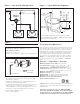
C.3 Pipe recirculated tempered water return so it connects
to hot water source and cold side of Tempering valve
(see Product Guide for piping details)
D.1 Readjust valve temperature per installation instructions
E.1 Clean check valves/filters
F.1 Reduce water velocity with pressure regulating valves
F.2 Check flow required versus rated flow capacity of valve
G.1 Open shutoffs or restore hot and cold supply
G.2 Clean check valves and filters
H.1 Stabilize water pressure with pressure regulating valves
H.2 Clean check valves and filters
Water temperatures in excess 110ºF (43ºC) are dangerous and may cause
scalding, severe injury or death! This valve can be adjusted to deliver water
at temperatures exceeding 110ºF (43ºC). Consequently, when used in an
ASSE 1016, ASSE 1069 or ASSE 1070 application, the installer must check
the mixed water outlet temperature at the point of use and adjust the Watts
Thermostatic Tempering Valve Series MMV or LFMMV to ensure delivery of
water at a safe temperature not exceeding 110ºF (43ºC). Mechanical valves are
not fail-safe. Due to the effects of various water conditions, periodic verification
of outlet water temperature is required.
When used in an ASSE 1017 application at the hot water source, the Watts
Thermostatic Tempering Valve Series MMV or LFMMV cannot be used by itself to
control final temperature at fixtures where ASSE Standard 1016, ASSE 1069 or
ASSE Standard 1070 listed devices are required. Such use may result in severe
bodily injury (i.e. scalding or chilling) and/or death. Additional ASSE Standard
1016, ASSE Standard 1069 or ASSE Standard 1070 listed devices, such as Watts
Series L111, LFL111, USG, LFUSG, MMV or LFMMV should be used at fixtures
to prevent possible injury.
Recirculation systems should recirculate water at temperatures over 140ºF to
reduce the risk of bacterial growth in the piping. This valve should not be used
to achieve these elevated temperatures. This valve can be used at fixtures in
conjunction with recirculation systems to reduce the system’s hot water to a safe
temperature at the point of use.
IMPORTANT
WARNING
!