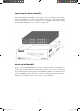
.Unpacking the Waves MaxxBCL After unpacking the MaxxBCL unit, please check it carefully for any damage. If any damage is found, immediately notify the carrier that brought you the package. You, the consignee, must instigate any claim. Please retain all packaging in case of future re-shipment. Mounting the MaxxBCL Before connecting MaxxBCL, be sure to securely mount it in a standard 19” studio rack-mount away from heat and moisture.
maxxBclManualFinal.
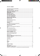
TABLE OF CONTENTS Important Safety Considerations ............................................................. 4 Package Content ..................................................................................... 4 Unpacking the Waves MaxxBCL ............................................................... 5 Mounting the MaxxBCL............................................................................. 5 Introduction ......................................................................................
Example B: MaxxBCL as a drum/bass controller (inserted in a subgroup where drums or/and bass assigned to) .......................................................................................................................................... 26 Example C: Digital mixing desk insert/FX (recording/mixing) ......................................................... 26 Example D: Using MaxxBCL as a D/A converter (for monitoring) .................................................... 27 Connection ...............
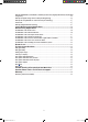
Please Read First! Warning – Safety First! Please read, complete and return by mail the Warranty Registration Form entitling you to technical support and service-under-warranty. NOTE: THE POWER SUPPLY IS NOT AUTO-SWITCHING! You must check to make sure the voltage rating shown directly on the back panel of your Waves MaxxBCL is appropriate for your power connection. Please see the diagram below. To change voltage, gently pull out the fuse holder.
Warning: Class 1 laser product (single-mode). Important Safety Considerations 1. Securely mount the Waves MaxxBCL in a 19” studio rack away from rain, moisture, liquids, heat sources or fire using the four supplied mounting bolts. (Plastic washers are provided to prevent scratching). Apply the rubber feet for desktop use. 2. In case of damage to the Waves MaxxBCL due to spilled liquids or physical damage from knocks or dropping, repairs should be performed by qualified service personnel only. 3.
Unpacking the Waves MaxxBCL After unpacking the MaxxBCL unit, please check it carefully for any damage. If any damage is found, immediately notify the carrier that brought you the package. You, the consignee, must instigate any claim. Please retain all packaging in case of future re-shipment. Mounting the MaxxBCL Before connecting MaxxBCL, be sure to securely mount it in a standard 19” studio rack-mount away from heat and moisture.
Introduction Welcome to the Maxx BCL User Manual. Be sure to read the safety considerations on page 3 of this manual before you plug-in and switch on the MaxxBCL’s power. Thank you for choosing the Waves MaxxBCL. Please spend some time reading through this manual so that you obtain the best possible performance from the unit. All Waves products are carefully designed and engineered for cutting-edge performance and world class reliability.
MaxxBCL Applications The MaxxBCL performs all digital processes with 48-bit internal precision (double precision). The internal processing is followed by requantization (wordlength reduction) from the internal 48-bit data to 16 or 24-bit output wordlengths. (Analog output always used the full 24-bit wordlength). The system can also be used to requantize 24-bit input signals to 16-bit (via the digital outputs only).
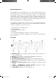
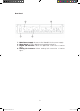
Rear Panel 1. Main Power Supply: Connects the MaxxBCL to the power supply. 2. Word Clock: Provides digital synchronization interface. 3. Digital I/O Interface: Allows for digital I/O connection of various types. 4. Analog I/O Interface: Allows analog I/O connection of various types. 8 maxxBclManualFinal.
Connecting The MaxxBCL Main Power Supply Important! 100, 120, 220 or 240 volt selectable - THE POWER SUPPLY IS NOT AUTO-SWITCHING! You must check to make sure the voltage rating shown on the back panel of your MaxxBCL is appropriate for your power connection. Please see the “Read First!” section. The power cable socket and fuse-holder with voltage selector are located together on the back panel of MaxxBCL. Plug the supplied cable into the back of the MaxxBCL and into your power connection.
Audio Connections (Rear Panel) Analog Connections: MaxxBCL accepts two types of connectors for left and right analog and outputs. The connector types are: 1. XLR/TRS combo inputs connector type for balanced / eunbalanced inputs. 2. XLR connector type for balanced outputs. 3. TRS (1/4”) jack connector type for balanced or unbalanced outputs. Digital Connections: The MaxxBCL accepts three types of digital inputs and outputs: 1. XLR type input/output connectors for AES/EBU signals. 2.
Input/Output Calibration controls: The Calibration controls allow you to calibrate the signal output that runs from your analog device (going to the MaxxBCL) to the MaxxBCL’s input, and the analog output of the MaxxBCL (going to the unit following the MaxxBCL in the signal chain). This allows you to get the maximum headroom available in your audio working environment.
Sync & Word Clock Connections (Rear Panel): The MaxxBCL can be connected to an external word clock source or you can use MaxxBCL’s internal clock source. The external clock source connector is BNC type. An external word clock is utilized for applications that require synchronization with other digital audio devices. The internal clock setting is selected on the front panel only when using the MaxxBCL’s analog inputs.
Operating the MaxxBCL MaxxBCL Overview The MaxxBCL is a hardware version of a commonly used software-based mastering chain used by mastering engineers worldwide. It consists of a Waves Renaissance Compressor (RenComp), the 2nd generation MaxxBass™ and the L2 Ultramaximizer plug-ins. We have found that the technique of maximizing levels and enhancing low-end perception gives great results in the world of live sound.
Opto The ‘Opto’ mode is actually the inverse of Electro. Opto-coupled behavior always “puts on the brakes” as the gain reduction approaches 0dBFS, i.e., the release time gets slower as the “needle comes back to zero”. As in Electro, this is true only when the gain reduction is less than 3dB. ARC™ is a system designed to dynamically choose the optimal release value for a wide-ranging input. ARC™ reacts much the way a human ear expects, and can produce increased RMS level with greater clarity.
Bass Enhancement with MaxxBassTM MaxxBass™ generates harmonics that are selectively added to the signal. These harmonics cause the ear to perceive low bass frequencies that may not actually be present in the signal. This psychoacoustic phenomenon, explained below in further detail, is used in a mixing or mastering situation to enhance the bass response of the target playback system. Even in a good mix, MaxxBass™ will create a fatter, clearer and overall better bass presence.
rumble from your venue. When the target speakers are unknown, or they consist of a range of speakers, switching the HPF off and retaining the original low frequencies allows for a more flexible compromise that can suit a wider range of speakers. This is useful when you master a CD or have a PA system with several types of speakers. When using MaxxBass™ on a PA system it is immediately noticeable that the system produces more bass while load is reduced.
About level and resolution in the L2 Maximum level The maximum level of a digital signal is generally governed by the source’s highest peak. Today’s demanding production environments require the average levels to be much higher than in the past, and with the accompanying risk of digital clipping comes the need for precision control of the maximum peak level. The L2’s brickwall peak limiter acts as a ‘protected gain’ control.
Controls & Displays Front Panel Controls Sample Rate: Select / Display the MaxxBCL sampling rate. MaxxBCL supports operating sample rates up to 96kHz. You can only change the signal sample rate when the MaxxBCL’s Sync mode is set to Internal. At the other settings the MaxxBCL locks to the digital stream or external Word Clock source. The MaxxBCL will automatically detect and display the sample rate for all other Sync modes. Options: 44.1kHz, 48kHz, 88.2kHz, 96kHz.
Presets: The MaxxBCL utilizes a preset system that allows you to store and recall up to 4 user made presets of the MaxxBCL processing parameters. To recall a preset press the button of the desired preset number. The recalled preset’s LED will light up to indicate the currently active preset. To store a preset, press the preset button where you wish to store the current setting, and hold the button down for 2 seconds. The preset’s LED will blink twice to indicate the preset was stored.
Input Input Meters: Display the input/ signal level on 2 channels, left and right. Input bar graph range: 0.0 to -90.0dB. Peak: Selects the behavior of the Peak Hold and resets the meter peak holding indication. A short press on the Peak button resets the peak readings on all the meters (input, output and attenuation). A long press on this button toggles the behavior of the peak hold indicator between infinite hold and 2 second hold. Options: inf = infinite peak holding, 2sec = 2 seconds peak holding.
Compressor Controls Bypass: Bypass is used to toggle the Compressor On/Off. It allows you to compare the original signal with the compressed one. Options: LED on=bypass on, LED off=bypass off. Opto/Elct: Toggles the Compressor behavior between Opto and Electro. Elct: Electro mode has a release time behavior that is increasingly faster as the gain reduction approaches zero, but only when gain reduction is less than 3dB.
compression starts acting to a significant degree. The value is in dB below 0dBFS. Compressor threshold range : 0 – 60 dB, step 0.1 Comp4Bass/Bass4Comp: Switches the order of the two processors in the processing chain. The L2 is always at the end of the signal chain, while the RenComp and MaxxBass™ can be first or second in the chain.
MaxxBass™ Controls Bypass: Toggles the MaxxBass™ processing On/Off. Options: LED on=bypass on, LED off=bypass off. HPF: The HPF is a High Pass Filter which is inserted on the original input signal. By switching the HPF on and off you can decide whether to retain or remove the original low frequencies. Options: LED on = original bass out, LED off = original bass in Frequency: Controls the MaxxBass™ Cutoff frequency, below which the processing begins.
Limiter Controls Bypass: Toggles the Limiter On/Off Options: LED on=bypass on, LED off=bypass off. Link: Links the Threshold & Out Ceiling controls together. When on, rotating either of the controls will change both values, while retaining their relative settings (from the time Link was turned on). This will have the effect of lowering the Threshold without changing the makeup gain. Options LED on=Link on, LED off=Link off. Threshold: Sets the level above which limiting starts.
Examples of Applications Example A: Using the MaxxBCL as a Sound Reinforcement (SR) enhancing module Connection: Connect your analog/digital stereo sum to the MaxxBCL analog/digital inputs (select the proper input format using the input selector). Connect the MaxxBCL’s analog outputs to your Crossovers/PA inputs. Use the MaxxBCL parallel outputs feature in order to record the processed signal to a CD/DAT recorder or to feed a broadcast console.
Example B: MaxxBCL as a drum/bass controller (inserted in a subgroup where drums and/or bass are assigned) Connection: Using an insert cable, Connect the insert point on your console to the MaxxBCL’s analog inputs and outputs. Aside from its usual peak limiting functions, the MaxxBCL also can be a great FX (effects) processor capable of truly slamming your drums or turning a wimpy bass sound into a huge low end.
Example D: Using MaxxBCL as a D/A converter (for monitoring) Connection: Connect the output from a DAW or computer sound card to the MaxxBCL’s digital inputs. Connect the MaxxBCL’s analog outputs to your monitoring system. If you want to monitor directly from the MaxxBCL and use IDR™ to reduce the wordlength, say for 16-bit DAT recording of masters, then you must set the IDR™ controls to the Quantize value for your master recorder. In the case of a DAT, set Quantize=16.
Here are the basic steps for using the MaxxBCL in a 16-bit/44.1kHz application: (These steps would also apply to 24-bit mastering) Please note that if you want to use MaxxBCL as your final peak limiter and re-quantizer, all processing, EQ, sample rate conversion, dynamic changes, etc. MUST be done before the final peak limiter re-quantizer processing. Thus, the MaxxBCL should be the last process before your Master Recorder, or before bouncing to a Production Master file.
differently than in a smaller system that is incapable of putting out these low frequency signals. In a small system (like those used in clubs and small performance halls) the RenComp gives color to the overall mix. The MaxxBass™ and the HPF allow the engineer to filter out the low frequencies that often create rumbling in smaller venues, while increasing the perception of bass.
Broadcasting Applications The MaxxBCL for live music Connect the output from the music mix console to the MaxxBCL’s analog or digital inputs (select the proper input format using the input selector). Connect the MaxxBCL outputs to an input on the broadcast console. The MaxxBCL Limiter section provides the necessary brick wall limiting for unpredictable live music situations.
The MaxxBCL used on the output of a DJ mixer Connect the output from the DJ mixer to the MaxBCL’s analog or digital inputs (select the proper input format using the input selector). Connect the MaxxBCL outputs to an input on the broadcast console. The Compressor section coupled with the Ultramaximizer of the Limiter section can produce an extreme sound with lots of punch. The MaxxBCL for broadcast production The MaxxBCL can be connected in various ways in the production room.
The MaxxBCL used to increase overall station signal loudness and bass Connect the output of the station automation system or broadcast console to MaxxBCL’s analog or digital inputs (select the proper input format using the input selector). Connect the MaxxBCL outputs to the input of the studio transmitter link. Here the amount of bass enhancement, compression and limiting is completely up to the engineer and how extreme the signal needs to sound.
The MaxxBCL for loading music into automation systems Connect the output from the CD player to the MaxxBCL’s analog or digital inputs (select the proper input format using the input selector). Connect the MaxxBCL outputs to an input to the broadcast automation system. This use of the MaxxBCL provides a superior way to smooth out the differences in recorded material to give a more even sound to the music archive.
Technical Specifications Maximum Analog Input Gain: 24 dBu Input Impedance, Balanced Input: 32 kOhm @ 1kHz ADC (@44.1kHz): Frequency response: 10Hz - 24 kHz / -0.1dB @ 10Hz ÷ 0.01@24k THD + Noise: < 0.0006 % (-104 dB) @ 1kHz -1dBFS THD 3rd Harmonic: -126 dBFS @1kHz, -10dBFS DAC (@44.1kHz): Frequency response: 20Hz-21kHz / - 0.4dB@20Hz ÷ 0.05dB@21kHz Noise: < -108 dB (unweighted) THD+Noise: < 0.
Front panel dedicated buttons: I/O selector: Analog, AES (XLR), S/PDIF (RCA/Optical) Sync: Internal, Digital, external word sync Sample Rates: 44.1, 48, 88.2, 96 kHz Quantize: 16-bit, 24-bit Peak (short click): Resets all infinite peak hold metering on the MaxxBCL front panel Peak (Click and 2 Second hold): Toggles between peak holding modes Compressor Bypass: 48-bit hardwire bypass Opto/Electro: toggles between 2 compressor behaviors Comp4Bass/Bass4Comp: Toggle effect chain Attack: 0.
Back Panel Analog input: XLR/1/4” Jack Combo Input Lift/Ground: Toggle Switch Analog output: Balanced XLR, unbalanced 1/4” 2-conductor phone plug Output Lift/Ground: Toggle Switch Digital input/output: AES (XLR), S/PDIF (RCA), S/PDIF (Optical) SPDIF output selector: Toggle Switch External word clock: BNC connector Word Clock Termination: Toggle Switch – 75Ω (On) / 1M Ω (Off) Main power supply: Linear Power Supply Adjustable Fuse: 100VAC, 110VAC, 220VAC, 240VAC.
therefore, the stereo image of these low level signals could be collapsed inward slightly. Such problems remove important auditory cues, reduce the apparent stereo image of low-level detail, and will slightly alter reverb quality, and more. Waves IDR™ has completely random L and R signals in order to preserve as much independent quality on each channel as possible.
One Year Limited Warranty on MaxxBCL Hardware: Waves Audio Ltd. (“Waves”) warrants that the Product conforms substantially to the specifications contained in the Product’s documentation for a period of one (1) year from the date of original purchase from Waves or its authorized resellers.
Some states do not allow the exclusion or limitation of certain warranties, so the above limitations may not apply to you. This warranty gives you specific legal rights. You may have other rights, which vary, state to state. Governing Law and Severability. This agreement will be governed by the laws of Israel. If a court finds any provision of this License unenforceable, that provision will be enforced to the maximum extent possible, and the remainder of the License shall continue in full force and effect.