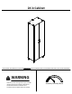
24 in Cabinet THIS INSTRUCTION BOOKLET CONTAINS IMPORTANT SAFETY INFORMATION. PLEASE READ AND KEEP FOR FUTURE REFERENCE. WARNING - Unit can tip over causing severe injury or death. - Anchor unit to stud in wall (if instructed to). - Do Not allow children to climb on unit. - Put heavy items on lower shelves or drawers.
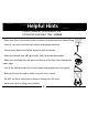
Helpful Hints PEOPLE NEEDED FOR ASSEMBLY: 1-2 ESTIMATED ASSEMBLY TIME: 1 HOUR - Open your item in the area you plan to keep it to avoid excessive heavy lifting. - Identify, sort and count the parts before attempting assembly. - Compression dowels are lightly tapped in with a hammer. - Slides are labeled with a R (right) and L (left) for proper placement. - Make sure to always face the point on the top of the Cam Lock towards the outer edge.
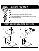
k Quic bly em Ass Tip Before You Start P P P P P Read through each step carefully and follow the proper order Separate and count all your parts and hardware Give yourself enough room for the assembly process Have the following tools: Flat Head Screwdriver, #2 Phillips Head Screwdriver and Hammer Caution: If using a power drill or power screwdriver for screwing, please be aware to slow down and stop when screw is tight. Failure to do so may result in stripping the screw.
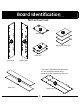
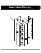
Board Identification Not actual size D F Bottom A B Adjustable Shelf (x3) E Shelf (x2) Left Panel Right Panel This piece is paperboard construction. It is not made from wood, but is required for the assembly of your unit.
Board Identification Not actual size This piece is paperboard construction. It is not made from wood, but is required for the assembly of your unit.
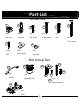
Part List Actual Size 1 2 6 5 4 3 (x8) (x8) (x8) (x4) (x4) cam lock cam bolt 5/8" screw 1-1/8" screw bolt 1-3/4" screw 8 7 (x4) 9 (x36) (x12) (x4) nail shelf support door pad Not Actual Size 12c 10 12a 11 12d (x2) (x4) handle adjustable foot 12b 12 (x1) safety bracket kit 13 (x6) hinge 6
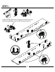
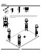
STEP 1 2 13 (x6) (x8) Detach the hinge plate from the hinge arm by lossen this screw. Attach the hinge plates to the "A" and "B" panels as shown.
STEP 2 1 12a Quick (x1) (x8) Assembly Tip 12b Proper orientation of CAM LOCK 12b Do not fully tighten this screw in this step.
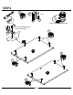
STEP 3 3 (x8) 3 4 11 4 (x4) (x4) Unscrew the two piece foot as shown. After top part of foot is attached to bottom shelf, screw on bottom part of foot. Be sure all four feet are level with each other.
STEP 4 E B E A UNLOCK LOCK 10 * raw edges are shaded
STEP 5 6 (x4) E E B A 6 6 D 6 11 * raw edges are shaded
STEP 6 IMPORTANT! THE BACK PANEL IS A STRUCTURAL PART OF THIS UNIT AND MUST BE INSTALLED PROPERLY. 7 (x36) Attached the back panel as shown nailing straight into the raw edges. Assure that the unit is square. Distance from corner to corner must be equal as shown. Assure that the unit is square. Distance from corner to corner must be equal as shown. 7 raw surface superficie cruda surface crue H WARNING Please make sure that the Backs are attached securely.
STEP 7 12c 12d (x1) 12d Option 2 Opción 2 L'option 2 hole agujero trou stud montante planche 12c Option 1 Opción 1 L'option 1 wallboard muro mur Option 1; Securely screw (12c) into solid area of the wall as shown. Option 2: Drill a 3/16" diameter hole (5mm) in the wallboard. Tap the wall anchor(12d) into the hole until it is flush. Fasten the wall bracket (12a) to the wall anchor (12d) with the screw (12c).
STEP 8 8 (x12) 8 8 8 8 8 F 8 8 F F 14 8
STEP 9 13 (x6) x2 G 13 15
STEP 10 10 5 (x2) (x4) Assistance of another person is advised in attaching the doors. G 10 5 5 x2 Repeat this step for installing the second door.
STEP 11 9 (x4) Position the rubber bumpers (9) on the edge of the top (C) and shelf (F) behind the doors (G).
STEP 12 Loosen screw A Adjust door. Tighten screw A Suelte el tornillo A Acomode la puerta. Ajuste el tornillo A Défaites le vis A Ajustez la porte. Serrez le vis A Loosen screw C Turn screw B to move door. Tighten screw C Loosen screw C Adjust door. Tighten screw C *side view Suelte el tornillo C Dé vuelta el tornillo B para mover la puerta. Ajuste el tornillo C Suelte el tornillo C Acomode la puerta. Ajuste el tornillo C *la vista lateral Défaites le vis C Le vis du tour B déplacer la porte.
Maximum Loads This unit has been designed to support the maximum loads shown. Exceeding these load limits could cause sagging, instability, product collapse, and/or serious injury. 0 lbs. 0 kg. 40 lbs. 18.1 kg. 35 lbs. 15.8 kg. 35 lbs. 15.8 kg. 50 lbs. 22.7 kg. Warning: Risk of injury to persons - do not place a television on this furniture. This furniture is not approved for use with a television. Certificate of Conformity 1. This certificate applies to product identified by this instruction manual. 2.
Español Cubierta Delantera Este libro de instrucciones contiene información IMPORTANTE de seguridad. Por favor lea y manténgalo para referencia en el futuro. PRECAUCION Este mueble puede volcarse y causar graves heridas y/o muerte. Anclar el mueble a un poste de madera en la pared (si esto se requiere). No Permita que los niños monten el mueble. Mantenga los artículos más pesados en los cajones de abajo.
Español Página 7 Separe la placa de bisagra del brazo de la bisagra perdiendo este tornillo. Una las placas de la bisagra (A) y (B) de los paneles como se muestra. Página 8 No apriete completamente este tornillo en este paso. Página 9 Desatornille el pie de dos piezas como se muestra. Despuéw de que la parte superior del pie se una al estante inferior, atornille en la parte inferior del pie. Esté weguro que los cuatro son nivelados el uno con el otro.
Español Página 19 CARGA MAXIMA Esta unidad ha sido diseñada para soportar la carga máxima anotada. El exceder estos límites puede causar inestabilidad, colapsarse y/o causar serias lesiones. ADVERTENCIA: Riesgo de lesiones a las personas - no coloque un televisor sobre muebles. Este mueble no está aprobado para su uso con un televisor.
Français Couverture Avant CE LIVRET D'INSTRUCTION CONTIENT DES INFORMATIONS IMPORTANTES SUR LA SÉCURITÉ. VEUILLEZ LIRE ET GARDER POUR UNE RÉFÉRENCE FUTURE ATTENTION Le meuble peut basculer et causer des blessures graves ou la mort. Ancrer le meuble à une planche murale dans le mur (si indiqué). Ne laissez pas les enfants grimper sur le meuble. Placez les articles lourds sur les étagères ou dans les tiroirs inférieurs.
Français Page 7 Détachez la plaque de charnière du bras de charnière par perte de cette vis. Fixez les plaques de charnière aux panneaux (A) et (B) comme montré. Page 8 Ne serrez pas complètement cette vis dans cette étape. Page 9 Dévissez la patte en deux parties comme montré. Après avoir fixé la partie supérieure de la patte à la tablette inférieure, vissez la partie inférieure de la patte. Assurez-vous que les quatre pattes sont au niveau entre elles.
Français Page 19 CHARGES MAXIMALES Ce meuble a été conçu pour supporter les charges maximales indiquées. En excédant ces limites de charge, le meuble pourrait devenir instable, s'effondrer, et/ou causer des blessures graves. AVERTISSEMENT : Risque de blessure corporelle - ne pas placer une télévision sur ce meuble. Ce meuble n'est pas approuvé pour une utilisation avec une télévision.