Certification Test Report 908.42 MHz Low Power Communication Device Transceiver 372 MHz Discrete Receiver FCC ID: KJ8-0001715 IC: 3540A-0001715 FCC Rule Part: 15.249 IC Radio Standards Specification: RSS-210 ACS Report Number: 07-0186 - 15C Manufacturer: Wayne-Dalton Corporation Model: 3790-Z Installation Guide Section4 5015 B.U.
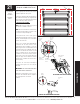
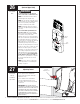
1 Tools Needed: Flat Tip Screwdriver Pliers/Wire Cutters Sensor Wire Installation (Required on 8000 Series Doors) Wire Routing Uncoil wires from photoelectric sensors and route wires up garage wall and along door header towards the right side of the opener. Route wires behind torque tube and tack wires in place with insulated staples (not supplied).Take care to run wires in a location where they will not interfere with the operation of the door. Do Not Staple Through Wire.
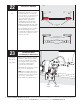
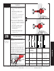
22 Tools Needed: Pliers Top View Safety Sensor Alignment Align the safety sensors by moving the sending and receiving units in or out until the alignment light on the receiving unit comes on. The 1/4”-20 carriage bolt can be loosened to move the safety sensor in or out, as required. If you have difficulty aligning the beams, check that both mounting brackets are mounted at the same height and remount if necessary. Additional minor adjustments can be made by slightly bending the mounting brackets.
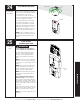
24 Tools Needed: Step Ladder Programming Light Fixture Press the red program button on the light fixture. The LED on the light fixture will turn on and remain on for 30 seconds or until a opener is learned to the light fixture. The incandescent lamp will also turn on when program button is pushed. LED Program Button FPO Light Button To Operate Pr e He s s re D r oo Press the light button on the wall station. This must be done within 30 seconds of pressing the program button on the light fixture.
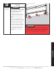
26 Tools Needed: None Install Routine (Custom Upper Limit) WARNING TO AVOID INJURY, NO ONE SHOULD CROSS THE PATH OF A MOVING DOOR! NOTE: If no obstruction interferes with a standard upper limit, skip this step. NOTE: The door must be in its fully closed position and the disconnect handle must be in the motor operated position (upper position) to initiate the profile routine. NOTE: Install profile will not run if safety sensors are not aligned (Only if required for your door).
Adjusting Detent (Continued) Tools Needed: a. If the motor does not pivot down, or only pivots down partially, the detent pin is set too hard. Using a flat tip screwdriver, turn the detent pin counterclockwise in 1/8 turn increments. Operate the door to confirm adjustment. Repeat procedure until motor pivots to full down position when the door is completely closed. a b b.
Lock Arm Installation (Continued) Tools Needed: Once track radius has been determined, secure the lock arm to the motor with (1) 5mm x .8mm phillips pan head screw. Lock Arm Motor NOTE: If unsure of track radius, begin with lock arm in position 1. After assembly of the lock arm, manually raise and lower the door and verify that the lock arm does not interfere with the door. If there is interference between the door and the lock arm, see Page 43 for lock arm troubleshooting.
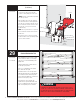
30 Tools Needed: 6” Height Object Testing the Safety Sensors (If Installed) WARNING WHEN PERFORMING THIS PART OF THE TEST, DO NOT PLACE YOURSELF UNDER DESCENDING DOOR, OR SEVERE OR FATAL INJURY MAY RESULT. Starting with the door fully open, place a 6” high object on the floor, in line with sensors, one foot from the left side of the door. Activation of the opener with the wall station Up/Down button should cause the door to move no more than one foot, stop and then reverse to fully open position.
❉ IMPORTANT SAFETY INSTRUCTIONS WARNING TO REDUCE THE RISK OF SEVERE INJURY OR DEATH: 1. READ AND FOLLOW ALL INSTRUCTIONS. 2. Never let children operate or play with the door controls. Keep remote controls away from children. 3. Always keep a moving door in sight and keep people and objects away until it is completely closed. NO ONE SHOULD CROSS THE PATH OF A MOVING DOOR. 4. NEVER GO UNDER A STOPPED, PARTIALLY OPEN DOOR. 5. Test the Door/Opener monthly.
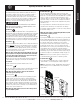
❉ Up-Down Button: Backlit LED Light: Momentarily pressing the Up/Down button activates the door. If an out-of-balance condition causes the door to stop while opening or reverses the door while closing, apply constant pressure to the Up/Down button until the door is fully open or closed. This will allow the opener to move the door in an out of balance condition, until the problem is corrected (see Troubleshooting). The Up/Down button (when unit is closed) can be activated by pressing flip cover.
❉ Programming HomeLink® System to the Torquemaster® idrive® (Primary) NOTE: This step can only be done on automobiles equipped with the HomeLink® system. Programming/Training HomeLink® Unit NOTE: Programming HomeLink® requires a Wayne-Dalton Transmitter that is programmed to the opener (the wallstation and transmitter(s) supplied with the opener, come pre-programmed from the factory). Any additional wallstation(s) or transmitter(s) will need to be programmed to the opener, see page 41.
NOTE: This Step can only be done on automobiles equipped with the HomeLink® system. Programming/Training HomeLink® Unit NOTE: Programming HomeLink® requires a Wayne-Dalton Transmitter that is programmed to the opener (the wallstation and transmitter(s) supplied with the opener, come pre-programmed from the factory). Any additional wallstation(s) or transmitter(s) will need to be programmed to the opener, see page 41. GARAGE DOOR MAY OPERATE DURING PROGRAMMING.
❉ Customizing the Settings Custom pet position: Normal install routine sets the pet position to approximately 8 inches above the ground. The pet opening height may be changed to open anywhere between 8” and 30” above the ground. To change the automatic pet opening height refer to the following procedure: NORMAL a. After completion of the normal install routine, with the door in the closed position, place the disconnect handle in the manual operated position.
❉ Customizing the Settings (Continued) Erasing Remote Controls: OPERATION CAUTION: MANUALLY DISCONNECT THE DOOR FROM OPENER USING THE EMERGENCY DISCONNECT HANDLE PRIOR TO ERASING REMOTE CONTROLS. Controls To clear programming of all remote control devices, press and hold the opener’s red program button for approximately 10 seconds. When the opener beeps 3 times, all remote controls are erased.
❉ Power Connection — Permanent Wiring Option d. Route opener power cable through the conduit. Strip 2 to 3 If required by local codes, the opener can be permanently wired. Services of a licensed electrician should be obtained, to permanently wire the Unit. Disconnect electrical power at fuse/breaker box. inches of outer jacket off power cable, insuring individual wire insulation is not nicked or cut. Strip approximately 3/4” of insulation off each individual wire.
❉ Tools Needed: None Programming Wireless Wall Station(s) or Transmitter(s) to Opener WARNING Motor in Up Position Handle In Manual Door Operated Position TO AVOID POSSIBLE SEVERE OR FATAL INJURY, MANUALLY DISCONNECT THE OPENER, USING THE EMERGENCY DISCONNECT HANDLE PRIOR TO PROGRAMMING REMOTE CONTROLS. Red Program Button NOTE: The opener can be activated by up to six remote control devices (including Wall Station, Transmitter, and Keyless Entry Devices).
✓ Troubleshooting Symptom Opener does not respond to the Wall Station or Transmitter. Probable Cause Corrective Action No power to the Opener. Check the Opener Power Cord to outlet connection. Controls are not programmed. See Activation and Programming section. Transmitter is not programmed. See Activation and Programming section. Weak or dead Transmitter battery. See Maintenance section for battery replacement. Wall Station is not programmed. See Activation and Programming section.
✓ Troubleshooting (Continued) Symptom Light fixture will not light during the door operation or by pressing the Wall Station light button. Probable Cause Corrective Action Faulty light bulb. Install new bulb (75W Max). No power to receptacle. Check circuit breakers. Opener not programmed to light. Program per Step 24. Motor does not pull fully up when using the Emergency Disconnect. Disconnect Cable has slipped inside of Handle. Re-install Handle per instructions in Step 9.
® ® Lifetime Limited Warranty idrive® for TorqueMaster® and TorqueMaster® Plus Subject to the terms and conditions contained in this Lifetime Limited Warranty, Wayne-Dalton Corp. (“Manufacturer”) warrants the opener, including electronic components (Batteries are not warranted), which is described at the top of this page, for a period of FIVE (5) YEARS from the date of installation against: (i) Any defects in material or workmanship.
Please Do Not Return This Product To The Store Call Us Directly! Our Trained Technicians Will Answer Your Questions and /or Ship Any Parts You May Need Call Us Toll-Free: (888) 827-3667 Thank you for your purchase www.wayne-dalton.com Please Do Not Return This Product To The Store. Call Us Directly! Our Trained Technicians Will Answer Your Questions and/or Ship Any Parts You May Need. You can reach us Toll Free at 1-888-827-3667 for Consumer Assistance or online at www.wayne-dalton.
✁ Cut-Out Template to Aid Installation Pre-drill 3/32” pilot hole Wall Station Template DRILL TEMPLATE 46 Pre-drill 5/64” pilot hole Keyless Entry Template
Patent Information Models: 3790/3790-Z/3791/3791-Z Covered under one or more of the following U.S.