9800 Series - 4 Section Low Head Room Front Mount TorqueMaster® - Single and Double Spring Installation Instructions and Owner’s Manual Wayne-Dalton, a Division of Overhead Door Corporation P.O. Box 67, Mt. Hope, OH 44660 www.Wayne-Dalton.com ©Copyright 2010 Wayne-Dalton, a Division of Overhead Door Corporation IMPORTANT NOTICE! Read these instructions carefully before attempting installation. If in question about any of the procedures, do not perform the work.
Table of Contents Important Safety Instructions................................................... 2 Package Contents.................................................................... 3 Door Section Identification....................................................... 4 Tools Required......................................................................... 5 Pre-Installation...................................................................5-10 Removing The Old Door........................................
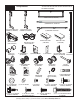
NOTE: Depending on the door model, some parts listed will not be supplied if not necessary. rear supports may or may not be included with your door.
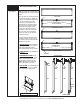
Door Section Identification Tools Needed: NOTE: This provides an alternative method for identifying your door sections/stacking position. Hinges are always pre-attached at the top of each section (except top section) and the hinges are stamped for identification, #1, #2, #3, and #4 (#4 only on five section doors). See view below. The stamp identifies the stacking sequence of the section. The sequence is always determined by #1 being the bottom section to #3 or #4 being the highest intermediate section.
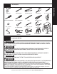
Power Drill Ratchet Wrench Pliers/Wire Cutters Tape Measure Phillips Head Screwdriver Flat Tip Screwdriver Pencil Needle Nose Pliers 7/16”, 1/2”, 9/16” Sockets 7/16” Socket Driver 7/16”, 1/2”, 3/8”, 9/16” Wrenches Safety Glasses Hammer vice grips vice clamps saw horses (pair) 1/8”, 3/16” Drill Bits gloves Step Ladder Removing An Old Door WARNING If your counterbalance system is other than those mentioned IN SECTIONS P1, P2 AND P3, do not attempt to work on it, but have a qualified door
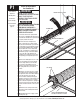
P1 Tools Needed: Approved Winding Bars 3/8” Wrench (2) Vice Clamps Recommended tools from page 5 Torsion Spring Removal For Standard Lift WARNING TORSION SPRING ASSEMBLY Failure to use approved winding bars can cause spring energy to be released suddenly, resulting in severe or fatal injury. WARNING COUNTERBALANCE SPRING TENSION MUST BE RELIEVED BEFORE REMOVING ANY HARDWARE. A POWERFUL SPRING RELEASING IT’S ENERGY SUDDENLY CAN CAUSE SEVERE OR FATAL INJURY.
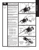
Tools Needed: Recommended tools from page 5 loosen lock nut counter gear/ cover A TorqueMaster® spring system can be identified by the end brackets. For single spring applications, the right hand end bracket will always have a drive gear, counter gear, counter cover, and a winding bolt head. The left hand end bracket will have no gears, counter cover, or winding bolt head. The hole for the winding bolt head will be plugged.
TorqueMaster® Spring Removal continued... Tools Needed: Recommended tools from page 5 (Spring Tube should be free to rotate in either direction.) If the counterbalance cable is still taut and the TorqueMaster® Spring Tube is difficult to rotate, that is an indication that spring tension still exists on the left hand spring. Repeat Steps 1 and 2 for releasing spring tension on the left hand side.
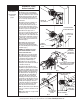
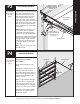
Tools Needed: Recommended tools from page 5 Extension Spring Removal Step 1: Raise the door to the fully open position and place vice clamps to the back legs of both vertical tracks, below the bottom rollers to prevent the door from falling. By opening the door you release most of the spring tension. Carefully unfasten the S-hook from the horizontal angle. Remove cable, sheave and extension spring. Repeat for the other side. If safety cables are running through the extension springs, remove them also.
P5 Tools Needed: Recommended tools from page 5 Preparing the Opening If you just removed your existing door or you are installing a new door, complete all steps in PREPARING THE OPENING. To ensure secure mounting of track brackets, side and center brackets, or steel angles to new or retro-fit construction, it is recommended to follow the procedures outlined in DASMA Technical Data Sheets #156, #161 and #164 at www.dasma.com.
Installation IMPORTANT: read instructions titled “p4” “REMOVING THE OLD DOOR” on page 9 and “P5” “preparing the opening” on page 10 before attempting door installation. IMPORTANT: Stainless steel or PT 2000 coated lag screws MUST be used when installing center bearing brackets, end brackets, jamb brackets, operator mounting/support brackets and disconnect brackets on treated lumber (preservative-treated). Stainless steel lag screws are NOT necessary when installing products on un-treated lumber.
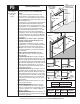
2 Tools Needed: None Fully Adjustable flagangle Attaching Fully Adjustable Flagangle to Vertical Track NOTE: If quick install flagangle was installed in Step 1, skip this step and continue with Step 3. If not, complete this step. 1/4”- 20 flange hex nuts Hand tighten the flagangle to the vertical track using (2) 1/4” - 20 x 9/16” large head ribbed track bolts (or stud plate if included) and (2) 1/4” - 20 flange hex nuts. Repeat for other side.
Tools Needed: None fully adjustable jamb brackets NOTE: If you have quick install jamb brackets, skip this step and continue Step 5. ST-0 The bottom jamb bracket is always the shortest bracket included with your door. If three jamb brackets are included with the door, the middle bracket on the track is the middle bracket in height. The top jamb bracket is the tallest bracket included. To attach the bottom jamb bracket, locate the lower hole/slot pattern of the vertical track.
5 Tools Needed: None Left hand TORQUEMASTER® counterbalance DRUM Drums IMPORTANT: Right and left hand is always determined from inside the garage looking out. NOTE: For door section identification see page 4. TorqueMaster® drums are marked right and left hand. Uncoil the counterbalance cables and make sure you place the right hand cable loop on the right hand milford pin and place the left hand cable loop on the left hand milford pin.
Tools Needed: 3/16” Drill Bit Power Drill 7/16” Socket Driver Tape Measure Level Vertical Track IMPORTANT: The tops of the vertical tracks must be level from side to side. If the bottom section was shimmed to level it. The vertical track on the shimmed side, must be raised the height of the shim. Position the left hand vertical track assembly over the rollers of the bottom section. Make sure the counterbalance cable is located between the rollers and the door jamb.
8 Tools Needed: Power Drill 7/16” Socket Driver Stacking Sections IMPORTANT: Push & hold the hinge leafs against section while securing with 1/4” - 14 x 5/8” self-tapping screws. End Hinges have (2) screws and Intermediate hinges have (3) screws. (3) 1/4” - 14 X 5/8” SELF-TAPPING SCREWS Intermediate hinge NOTE: Install lock at this time (sold separately) see instructions in OPTIONAL SIDELOCK INSTALLATION on page 33.
10 Tools Needed: Hammer 7/16” Socket 7/16” Wrench door width +3-3/8” to 3-1/2” Top Section Place the top section in the opening and vertically align with lower sections. Align vertical marks in the upper alignment sticker, with the lower alignment sticker on right hand side on the back of door. Ratchet Wrench Power Drill Temporarily secure the top section by driving a nail in the header near the center of the door and bending it over the top section.
11 Tools Needed: 7/16” Socket Ratchet Wrench 7/16” Wrench Level Attaching Horizontal Track to Quick Install Flagangle horizontal track NOTE: If you have fully adjustable flagangle, skip this step and complete Step 12. flagangle key slot QUICK INSTALL TAB To install horizontal track, align the key slot of the horizontal track with the quick install tab of the flagangle. Push curved portion of horizontal track down to lock in place.
12 Tools Needed: 7/16” Socket Ratchet Wrench 7/16” Wrench Level Flat Tip Screwdriver Attaching Horizontal Track to Adjustable Flagangle NOTE: If quick install flagangle was installed in Step 11, skip this step and continue with Step 13. If not, complete this step. To install horizontal track, place the curved end over the top roller. Align the bottom of the horizontal track with the vertical track. Hand tighten the horizontal track to the flagangle with (1) stud plate and (2) 1/4” - 20 flange hex nuts.
13 Tools Needed: Power Drill 7/16” Socket Driver Hammer Top Brackets top bracket assembly Remove, but retain (2-4) 1/4”- 14 x 7/8” self drilling screws from the right side of the u-bar, allowing enough room to slide the top bracket between the section and the u-bar. Insert a roller into the low headroom top bracket. Slide the low headroom top bracket assembly between the u-bar and section, as shown. Twist the roller into the upper track.
14 Tools Needed: None TorqueMaster® Spring Tube TorqueMaster® springs come lubricated and pre-assembled inside the Torquemaster® spring tube. To install, lay the Torquemaster® spring tube on the floor (inside garage) in front of the door with the labeled end to the left. Important: RIGHT AND LEFT HAND IS ALWAYS DETERMINED FROM INSIDE THE garage LOOKING OUT.
16 Tools Needed: None idrive® Installation NOTE: See idrive® main installation and owners manual for idrive® parts. IMPORTANT: Right and left hand is always determined from inside the garage looking out. Lay the TorqueMaster® spring tube on the floor (inside garage) in front of the door with the labeled end to the left. Look into the opener’s left side to ensure the left hand bearing and the internal (black) sleeve are aligned with the TorqueMaster® spring tube profile.
Tools Needed: None Cable Drum Installation Shake the TorqueMaster® spring tube gently to extend the winding shafts out about 5" on each side. For single spring applications, there will be no left hand spring in the TorqueMaster® spring tube. Lift the TorqueMaster® spring tube and rest it on the top of the flagangles. If idrive® opener is being installed, orient TorqueMaster® spring tube so the back of opener is flat against header/ mounting surface. NOTE: Cable drums are marked right and left hand.
18 Tools Needed: Lubricating Oil Drive Gear Installation Cable Drum Winding Shaft Splines Beginning with the right hand side, lubricate entire circumference of the drive gear with the lubricating oil provided. Slide the drive gear onto the winding shaft splines until it touches the flagangle. NOTE: On single spring applications, no drive gear is required on the left side. lubricating oil Flagangle NOTE: If additional lubricating oil is needed, use “Dura Lube® Engine Oil Treatment”.
20 Tools Needed: None Winding Shaft Inside End Bracket Counter Installation I nstall the right side counter gear, with the missing tooth toward the outside and away from the end bracket. Press the counter gear onto the end bracket until snaps engage. Select the right hand counter cover and align the hex of the counter cam with the end of the winding shaft. Also, align the “0” on the counter cover with the raised rib on the end bracket.
22 Tools Needed: Power Drill 1/8” Drill Bit 7/16” Socket Driver Positioning Support Bracket Antenna wire 45 angle NOTE: See idrive® main installation and owners manual for idrive® parts. NOTE: idrive® must be installed on a solid mounting surface. Locate the mounting surface. The mounting surface is a vertical board running directly above the center of the door. Remove (2) 1/4”-20 flange hex nuts from bottom of opener. TorqueMaster® spring tube SUPPORT BRACKET NOTE: Do not discard flange nuts.
23 Tools Needed: Pliers S-Hook Attaching Disconnect Cables Disconnect Cable NOTE: See idrive® main installation and owners manual for idrive® parts. Hole in Right End Bracket Attach the loose disconnect cable (located in opener hardware bag) to the opener with the “S” hook. Close both ends of the “S” hook with pliers, to lock assembly together. Thread the disconnect cable (behind the counterbalance cable) through the hole in the right hand end bracket.
25 Attaching Disconnect Handle Tools Needed: NOTE: See idrive main installation and owner’s manual for idrive® parts. Phillips Head Screwdriver Wire Cutters Emergency Disconnect Label ® Note: Bring motor to the down position by pulling the disconnect cable. Insure opener disconnect teeth are engaged before installing disconnect handle. Start the #6-20 x 1/2" screw into the disconnect handle. Thread the disconnect cable through the top of the disconnect handle bracket and then the disconnect handle.
26 Tools Needed: (2) Vice Clamps Securing Door for Spring Winding Place vice clamps onto both vertical tracks just above the third roller. This is to prevent the garage door from raising while winding counterbalance springs. WARNING Failure to place vice clamps onto vertical Tracks can allow door to raise and cause severe or fatal injury.
28 Tools Needed: Power Drill 7/16" Socket Driver Winding Bolt Rotation See chart in Step 29 for proper spring tension setting. Beginning with the right hand side, ensure the cable is in the first groove of the cable drum. Apply light pressure to the canoe clip on counter cover while winding springs. Winding Bolt WARNING P rior to winding or making adjustments to the springs, ensure you’re winding in the proper direction as stated in the Installation Instructions.
Tools Needed: None Drum wraps are identified as right and left hand. Outside Flange To install, place the right hand drum wrap over the cable drum and under the idrive® disconnect cable. Align the outside flange over the outside edge of the cable drum and push the drum wrap down onto the cable drum. Repeat for left hand side. Cable Drum NOTE: Drum wraps must be installed to prevent cable from becoming tangled.
Rear Support Continued... Tools Needed: horizontal tracks to the rear supports with 5/16”-18 x 1-1/4” hex bolts and nuts (may not be supplied). Horizontal tracks must be level and parallel with door. NOTE: If rear supports are to be installed over drywall, use 5/16” x 2” hex head lag screws. NOTE: If an idrive® opener is installed, position horizontal tracks one hole above level when securing it to rear supports. Adjust weather seal or door stop (if necessary).
Side Lock Tools Needed: Power Drill 7/16” Socket Driver Tape Measure Install the side lock on the second section of the door. Secure the lock to the section with (4) 1/4”- 20 x 11/16” self drilling screws. Square the lock assembly with the door section and align with the square hole in the vertical track. The side lock should be spaced in approximately 1/8” from the section edge. IMPORTANT: side locks must be removed or made inoperative in the unlocked position, if an operator is installed on the door.
DoorMaster Bracket TM Tools Needed: DoormasterTM bRACKET/ DRIVE GEAR ASSEMBLY a A NOTE: When installing a DoorMasterTM operator use the center bracket and drive gear supplied with your operator (located in DoorMasterTM package). Slide the DoorMasterTM bracket/drive gear assembly onto the TorqueMaster® spring tube, so that the drive gear/ center bracket assembly are in the center of the TorqueMaster® spring tube.
Trolley Operator Tools Needed: WARNING OPERATOR MUST BE TESTED AT TIME OF INSTALLATION AND MONTHLY THEREAFTER TO ENSURE THAT DOOR REVERSES ON CONTACT WITH 2 X 4 BOARD LAID FLAT UNDER THE DOOR. FAILURE TO ADJUST OPERATOR, IF NECESSARY, CAN RESULT IN SEVERE OR FATAL INJURY. IF YOUR OPERATOR IS EQUIPPED WITH A PHOTOELECTRIC EYE SYSTEM, THEN THIS MUST BE TESTED AT THE SAME TIME TO ENSURE THAT DOOR DOES NOT CLOSE AND A CLOSING DOOR OPENS IF PHOTOELECTRIC EYE SYSTEM IS OBSTRUCTED.
Cleaning Your Steel And Fiberglass Garage Door IMPORTANT: DO NOT USE A PRESSURE WASHER ON GARAGE DOOR! While factory-applied finishes on garage doors are durable, it is desirable to clean them on a routine basis. Some discoloration of the finish may occur when a door has been exposed to dirt-laden atmosphere for a period of time. Slight chalking may also occur as a result of direct exposure to sunlight. Cleaning the door will generally restore the appearance of the finish.
Steel Preparation For Painting Steel (Surface Preparation for Painting) Wax on the surface must be removed or paint peeling/flaking will result. To remove this wax, it will be necessary to lightly scuff the surface with a fine steel wool pad, saturated with soapy water. A final wipe and rinse should be done with clean water only, to remove any loose particles and any soapy film residue. Surface scratches, which have not exposed the metal substrate, can be lightly buffed or sanded with 0000 steel wool or No.
Lifetime Limited Warranty Model 9800 Subject to the terms and conditions contained in this Lifetime Limited Warranty, Wayne-Dalton (“Manufacturer”) warrants the sections of the garage door for as long as you own the door against: (i) The door becoming inoperable due to rust-through of the steel skin backer from the core of the door section, caused by cracking, splitting, or other deterioration of the steel skin, or due to structural failure caused by separation or degradation of the foam insulation.