OWNER'S MANUAL MODEL NO. S165H42C 16.5 HP 42 Inch Lawn Tractor For Parts and Service, contact our authorized distributor: call 1-800-849-1297 For Technical Assistance: call 1-800-829-5886 ® 178704 Rev. 1 4.16.01 TR PRINTED IN U.S.A.
SAFETY RULES Safe Operation Practices for Ride-On Mowers IMPORTANT: THIS CUTTING MACHINE IS CAPABLE OF AMPUTATING HANDS AND FEET AND THROWING OBJECTS. FAILURE TO OBSERVE THE FOLLOWING SAFETY INSTRUCTIONS COULD RESULT IN SERIOUS INJURY OR DEATH. I. GENERAL OPERATION • • • • • • • • • • • • • • • • • DO NOT: • Do not turn on slopes unless necessary, and then, turn slowly and gradually downhill, if possible. • Do not mow near drop-offs, ditches, or embankments.
SAFETY RULES Safe Operation Practices for Ride-On Mowers • • • • • • • • • • • • • • Be sure the area is clear of other people before mowing. Stop machine if anyone enters the area. Never carry passengers or children even with the blades off. Do not mow in reverse unless absolutely necessary. Always look down and behind before and while backing. Never carry children. They may fall off and be seriously injured or interfere with safe machine operation.
PRODUCT SPECIFICATIONS GASOLINE CAPACITY AND TYPE: 2.0 GALLONS UNLEADED REGULAR OIL TYPE (API-SF-SJ): SAE 30 (above 32°F) SAE 5W-30 (below 32°F) OIL CAPACITY: 3.4 PINTS SPARK PLUG: (GAP: .030") CHAMPION RN4C GROUND SPEED (MPH): FORWARD: REVERSE: 5.2 2.7 TIRE PRESSURE: FRONT: REAR: 14 PSI 12 PSI CHARGING SYSTEM: 3 AMPS BATTERY 5 AMPS HEADLIGHTS BATTERY: AMP/HR: MIN. CCA: CASE SIZE: BLADE BOLT TORQUE: 27-35 FT. LBS. CONGRATULATIONS on your purchase of a new tractor.
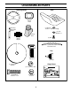
UNASSEMBLED PARTS Steering Wheel Seat Steering Wheel Insert Steering Extension Shaft (1) Washer 17/32 x 1-3/16 x 12 Gauge (1) Lock Washer 1/2 Steering Boot Steering Wheel Adapter (1) Bolt (1) Oil Drain Tube For Future Use Key (1) Hex Bolt 3/8-16 x 1 (2) Keys (1) Large Flat Washer Slope Sheet (1) Lockwasher 3/8 (1) Hex Bolt 5/16-18 x 1-1/4 (1) Locknut 5/16-18 5
ASSEMBLY Your new tractor has been assembled at the factory with exception of those parts left unassembled for shipping purposes. To ensure safe and proper operation of your tractor all parts and hardware you assemble must be tightened securely. Use the correct tools as necessary to insure proper tightness. TOOLS REQUIRED FOR ASSEMBLY INSERT A socket wrench set will make assembly easier. Standard wrench sizes are listed.
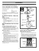
ASSEMBLY INSTALL SEAT (See Fig. 3) TO ROLL TRACTOR OFF SKID (See Operation section, for location and function of controls) Adjust seat before tightening adjustment bolt. • Remove adjustment bolt, lock washer and flat washer securing seat to cardboard packing and set aside for assembly of seat to tractor. • Pivot seat upward and remove from the cardboard packing. Remove the cardboard packing and discard. • Place seat on seat pan so head of shoulder bolt is positioned over large slotted hole in pan.
ASSEMBLY 3CHECKLIST CHECK TIRE PRESSURE BEFORE YOU OPERATE AND ENJOY YOUR NEW TRACTOR, WE WISH TO ASSURE THAT YOU RECEIVE THE BEST PERFORMANCE AND SATISFACTION FROM THIS QUALITY PRODUCT. PLEASE REVIEW THE FOLLOWING CHECKLIST: 3 All assembly instructions have been completed. 3 No remaining loose parts in carton. 3 Battery is properly prepared and charged. (Minimum 1 hour at 6 amps). 3 Seat is adjusted comfortably and tightened securely. 3 All tires are properly inflated.
OPERATION These symbols may appear on your tractor or in literature supplied with the product. Learn and understand their meaning.
OPERATION KNOW YOUR TRACTOR READ THIS OWNER'S MANUAL AND SAFETY RULES BEFORE OPERATING YOUR TRACTOR Compare the illustrations with your tractor to familiarize yourself with the locations of various controls and adjustments. Save this manual for future reference. ATTACHMENT CLUTCH LEVER IGNITION SWITCH LIGHT SWITCH POSITION LIFT LEVER PLUNGER THROTTLE/CHOKE CONTROL ATTACHMENT LIFT LEVER CLUTCH/BRAKE PEDAL PARKING BRAKE FREE WHEEL CONTROL MOTION CONTROL LEVER FIG.
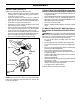
OPERATION The operation of any tractor can result in foreign objects thrown into the eyes, which can result in severe eye damage. Always wear safety glasses or eye shields while operating your tractor or performing any adjustments or repairs. We recommend a wide vision safety mask over spectacles or standard safety glasses. HOW TO USE YOUR TRACTOR • TO SET PARKING BRAKE (See Fig. 5) IMPORTANT: LEAVING THE IGNITION SWITCH IN ANY POSITION OTHER THAN "OFF" WILL CAUSE THE BATTERY TO BE DISCHARGED, (DEAD).
OPERATION TO ADJUST GAUGE WHEELS (See Fig. 6) TO OPERATE ON HILLS Gauge wheels are properly adjusted when they are slightly off the ground when mower is at the desired cutting height in operating position. Gauge wheels then keep the deck in proper position to help prevent scalping in most terrain conditions. • Adjust gauge wheels with tractor on a flat level surface. • Adjust mower to desired cutting height (See “TO ADJUST MOWER CUTTING HEIGHT” in the Operation section of this manual).
OPERATION • BEFORE STARTING THE ENGINE CHECK ENGINE OIL LEVEL • • • • • The engine in your tractor has been shipped, from the factory, already filled with summer weight oil. Check engine oil with tractor on level ground. Remove oil fill cap/dipstick and wipe clean, reinsert the dipstick and screw cap tight, wait for a few seconds, remove and read oil level. If necessary, add oil until “FULL” mark on dipstick is reached. Do not overfill.
OPERATION • Sitting in the tractor seat, start engine. After the engine is running, move throttle control to slow position. With motion control lever in neutral (N) position, slowly disengage clutch/brake pedal. • Move motion control lever to full forward position and hold for five (5) seconds. Move lever to full reverse position and hold for five (5) seconds. Repeat this procedure three (3) times. NOTE: During this procedure there will be no movement of drive wheels.
CUSTOMER RESPONSIBILITIES MAINTENANCE SCHEDULE FILL IN DATES AS YOU COMPLETE REGULAR SERVICE E GE RS S RS RS US OU SON ORA UR OU HOU H O T H A 0 S 8H SE 25 10 50 E E RY ERY ERY ERY ERY FOR OR E F SERVICE EV EV EV EV EV BE BE C EA H DATES Check Brake Operation Check Tire Pressure T R A C T 0 R Check Operator Presence and Interlock Systems Check for Loose Fasteners 7 Sharpen/Replace Mower Blades 4 Lubrication Chart Check Battery Level 6 Clean Battery and Terminals Check Transaxle Cooling Adjust Bl
CUSTOMER RESPONSIBILITIES TRACTOR TRAILING EDGE UP Always observe safety rules when performing any maintenance. MANDREL ASSEMBLY BLADE CENTER HOLE BRAKE OPERATION If tractor requires more than six (6) feet stopping distance at high speed in highest gear, then brake must be adjusted. (See “TO ADJUST BRAKE” in the Service and Adjustments section of this manual).
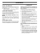
CUSTOMER RESPONSIBILITIES NOTE: Although multi-viscosity oils (5W30, 10W30 etc.) improve starting in cold weather, these multi-viscosity oils will result in increased oil consumption when used above 32°F. Check your engine oil level more frequently to avoid possible engine damage from running low on oil. Change the oil after every 25 hours of operation or at least once a year if the tractor is not used for 25 hours in one year.
CUSTOMER RESPONSIBILITIES AIR FILTER MUFFLER Your engine will not run properly using a dirty air filter. Remove cartridge every 25 hours of operation and tap to clean. Replace paper cartridge once a year or after every 100 hours of operation, more often if used in very dusty, dirty conditions. • Remove knobs and cover. • Remove foam pre-cleaner element by sliding it off of the paper cartridge. NOTE: Do not attempt to clean or oil the paper cartridge.
SERVICE AND ADJUSTMENTS CAUTION: BEFORE PERFORMING ANY SERVICE OR ADJUSTMENTS: • Depress clutch/brake pedal fully and set parking brake. • Place motion control lever in neutral (N) position. • Place attachment clutch in “DISENGAGED” position. • Turn ignition key “OFF” and remove key. • Make sure the blades and all moving parts have completely stopped. • Disconnect spark plug wire from spark plug and place wire where it cannot come in contact with plug. TRACTOR • • TO REMOVE MOWER (See Fig.
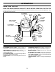
SERVICE AND ADJUSTMENTS NOTE: Three full turns of adjustment nut will change mower height about 1/8". • Recheck measurements after adjusting. BOTH FRONT LINKS MUST BE EQUAL IN LENGTH BOTTOM EDGE OF MOWER TO GROUND BOTTOM EDGE OF MOWER TO GROUND “A” “A” GROUND LINE NUT "E" FIG. 17 NUT "F" TRUNNION SUSPENSION ARM FRONT LINKS LIFT LINK ADJUSTMENT NUT FIG. 20 FIG. 18 TO REPLACE MOWER BLADE DRIVE BELT (See Fig. 21) FRONT-TO-BACK ADJUSTMENT (See Figs.
SERVICE AND ADJUSTMENTS • • • • Depress clutch/brake pedal and engage parking brake. Measure distance between brake operating arm and nut “A” on brake rod. If distance is other than 1-9/16", loosen jam nut and turn nut “A” until distance becomes 1-9/16". Retighten jam nut against nut “A”. Road test tractor for proper stopping distance as stated above. Readjust if necessary. If stopping distance is still greater than six (6) feet in highest gear, further maintenance is necessary.
SERVICE AND ADJUSTMENTS TO REMOVE WHEEL FOR REPAIRS (See Fig. 25) NEGATIVE TERMINAL POSITIVE TERMINAL • • Block up axle securely. Remove axle cover, retaining ring and washers to allow wheel removal (rear wheel contains a square key - Do not lose). • Repair tire and reassemble. • On rear wheels only: align grooves in rear wheel hub and axle. Insert square key. • Replace washers and snap retaining ring securely in axle groove. • Replace axle cover.
SERVICE AND ADJUSTMENTS ENGINE KEPS NUT HEX BOLT POSITIVE (RED) CABLE TO ADJUST THROTTLE CONTROL CABLE (See Fig. 30) The throttle control has been preset at the factory and adjustment should not be necessary. Check adjustment as described below before loosening cable. If adjustment is necessary, proceed as follows: • With engine not running, move throttle control lever from slow to choke position. Slowly move lever from choke to fast position.
STORAGE Immediately prepare your tractor for storage at the end of the season or if the tractor will not be used for 30 days or more. ENGINE FUEL SYSTEM CAUTION: Never store the tractor with gasoline in the tank inside a building where fumes may reach an open flame or spark. Allow the engine to cool before storing in any enclosure. IMPORTANT: IT IS IMPORTANT TO PREVENT GUM DEPOSITS FROM FORMING IN ESSENTIAL FUEL SYSTEM PARTS SUCH AS CARBURETOR, FUEL FILTER, FUEL HOSE, OR TANK DURING STORAGE.
TROUBLESHOOTING POINTS PROBLEM CAUSE Will not start 1. 2. 3. 4. 5. 6. 7. Out of fuel. Engine not “CHOKED” properly. Engine flooded. Bad spark plug. Dirty air filter. Dirty fuel filter. Water in fuel. 1. 2. 3. 4. 5. 6. 7. 8. 9. Loose or damaged wiring. Carburetor out of adjustment. 8. 9. 10. Hard to start CORRECTION Engine valves out of adjustment. 10. Fill fuel tank. See “TO START ENGINE” in Operation section. Wait several minutes before attempting to start. Replace spark plug.
TROUBLESHOOTING POINTS PROBLEM CAUSE CORRECTION Engine continues to run when operator leaves seat with attachment clutch engaged 1. Faulty operator-safety presence control system. 1. Check wiring, switches and connections. If not corrected, contact an authorized service center/ department. Poor cut - uneven 1. 2. 3. 4. 5. Worn, bent or loose blade. Mower deck not level. Buildup of grass, leaves, and trash under mower. Bent blade mandrel.
TRACTOR - - MODEL NUMBER S165H42C SCHEMATIC RED BLACK BATTERY RED A RED FUSE AMMETER (OPTIONAL) M STARTER BLACK WHITE SOLENOID RED B S G BLACK L M CLUTCH / BRAKE (PEDAL UP) A1 A2 WHITE SEAT SWITCH (NOT OCCUPIED) IGNITION SWITCH WHITE BLACK BLACK BLACK BLACK HOUR METER ATT'MENT CLUTCH (CLUTCH OFF) GROUNDING CONNECTOR (OPTIONAL) BLUE SPARK PLUG GAP (2 PLUGS ON TWIN CYL.
REPAIR PARTS TRACTOR - - MODEL NUMBER S165H42C ELECTRICAL 21 22 42 24 41 43 27 27 40 26 27 27 81 81 81 25 16 16 33 30 D. C.
REPAIR PARTS TRACTOR - - MODEL NUMBER S165H42C ELECTRICAL KEY NO. PART NO.
REPAIR PARTS TRACTOR - - MODEL NUMBER S165H42C CHASSIS AND ENCLOSURES 212 17 30 24 29 18 24 26 12 28 25 26 25 5 53 51 52 5 31 3 55 209 57 9 11 208 207 15 209 209 20 23 8 54 209 207 6 26 1 16 13 3 35 145 37 37 33 10 3 35 2 34 205 26 38 206 208 3 205 38 30
REPAIR PARTS TRACTOR - - MODEL NUMBER S165H42C CHASSIS AND ENCLOSURES KEY NO. PART NO.
REPAIR PARTS TRACTOR - - MODEL NUMBER S165H42C DRIVE 51 57 89 63 212 70 69 197 161 159 158 59 65 162 169 198 61 14 164 48 42 40 82 165 156 38 166 42 35 49 47 62 36 52 16 39 8 30 120 34 52 36 35 37 32 53 95 28 30 103 61 26 205 26 16 29 16 84 27 22 77 24 55 19 25 26 199 200 15 61 96 26 75 77 1 151 51 27 21 32 150 41 168 163 10 202 50 64 56 83 171 81 61 116 66 74 75 78 61 71 73 76 32 16
REPAIR PARTS TRACTOR - - MODEL NUMBER S165H42C DRIVE KEY NO. PART NO.
REPAIR PARTS TRACTOR - - MODEL NUMBER S165H42C STEERING ASSEMBLY 38 63 11 39 1 41 42 37 37 36 44 51 54 88 91 43 71 68 67 67 29 46 29 8 47 6 9 17 67 13 65 46 85 2 8 7 85 6 9 9 5 47 7 3 32 9 5 68 11 82 29 26 4 43 15 40 15 43 29 28 15 10 30 34 6 8
REPAIR PARTS TRACTOR - - MODEL NUMBER S165H42C STEERING ASSEMBLY KEY NO. PART NO.
REPAIR PARTS TRACTOR - - MODEL NUMBER S165H42C ENGINE 3 2 13 4 1 38 62 85 78 16 81 14 32 78 44 46 33 45 37 33 31 23 40 29 OPTIONAL EQUIPMENT Spark Arrester KEY PART NO. NO. 1 170551 2 17720410 3 -----4 13 14 16 23 29 31 32 137351 149272 148456 11050600 169837 137180 174642 161493 DESCRIPTION Control Throt/Ch Screw Hex Thd Cut 1/4-20x5/8 T Engine Tec, Model OHV165 (Order parts from engine manufacturer) Muffler Tec 13.
REPAIR PARTS TRACTOR - - MODEL NUMBER S165H42C MOWER LIFT 7 8 5 1 3 13 2 4 6 6 11 5 4 12 13 19 20 13 15 31 32 20 15 13 KEY NO. 1 2 3 4 5 6 7 8 11 12 13 19 20 17 18 20 16 31 32 PART NO. 159460 159471 105767X 12000002 19211621 120183X 109413X 124526X 139865 139866 4939M KEY NO. 15 16 17 18 19 20 31 32 DESCRIPTION Wire Asm Inner/Sprg w/Plunger Shaft Asm Lift Pin Groove E Ring #5133-62 Washer 21/32 x 1 x 21 Ga.
REPAIR PARTS TRACTOR - - MODEL NUMBER S165H42C SEAT ASSEMBLY 1 8 8 9 14 9 7 7 10 5 6 22 21 2 24 5 26 16 25 15 23 4 13 17 3 12 KEY NO. PART NO. DESCRIPTION KEY NO. 1 2 3 4 5 6 7 8 9 10 12 13 140116 140551 71110616 19131610 145006 73800600 124181X 17000616 19131614 174894 121246X 121248X Seat Bracket Pnt Pivot Seat (blk ) Bolt Washer 13/32 x 1 x 10 Ga Clip Push-In Hinged Nut Spring Seat Cprsn 2 250 Blk Zi Screw 3/8-16 x 1.
REPAIR PARTS TRACTOR - - MODEL NUMBER S165H42C DECALS 9 3 2 12 7 7 4 10 12 16 1 11 5 8 6 20 14 KEY NO. 1 2 3 4 5 6 7 8 9 PART NO. 156868 162970 164578 164579 179128 179285 164425 178392 171448 DESCRIPTION KEY NO. Decal Instruction Operat English Decal Ins Strg Wh Decal Hood Rh Decal Hood Lh Decal Deck “B” “Y2” Decal Engine Decal Panel Side Decal Disconnect Decal Fender Logo 10 11 12 14 16 20 ---- PART NO.
REPAIR PARTS TRACTOR - - MODEL NUMBER S165H42C MOWER DECK 68 40 37 36 40 67 157 158 156 153 151 143 155 144 45 150 40 37 159 152 46 153 154 145 44 59 56 53 52 55 51 48 147 54 142 49 50 148 90 91 146 33 32 31 93 94 93 95 30 34 21 90 21 1 147 2 21 142 26 2 16 28 15 14 119 118 20 3 18 149 114 13 6 11 19 27 29 18 4 21 24 25 115 5 22 23 113 111 114 116 117 21 112 115 118 10 9 8 40 119 113 117 116
REPAIR PARTS TRACTOR - - MODEL NUMBER S165H42C MOWER DECK KEY NO. PART NO.
LIMITED WARRANTY The Manufacturer warrants to the original consumer purchaser that this product as manufactured is free from defects in materials and workmanship. For a period of two (2) years from date of purchase by the original consumer purchaser, we will repair or replace, at our option, without charge for parts or labor incurred in replacing parts, any part which we find to be defective due to materials or workmanship. This Warranty is subject to the following limitations and exclusions. 1.
SUGGESTED GUIDE FOR SIGHTING SLOPES FOR SAFE OPERATION SIGHTING GUIDE CUT OUT ON D THIS OTT IS A ED L 15 S INES LOP E ONLY RIDE UP AND DOWN HILL, NOT ACROSS HILL 43 SIGHT AND HOLD THIS LEVEL WITH SKY LINE OR TREE. 15 MAX. Operate your Tractor up and down the face of slopes (not greater than 15 ), never across the face. Make turns gradually to prevent tipping or loss of control. Exercise extreme caution when changing direction on slopes.
®