Motors | Automation | Energy | Transmission & Distribution | Coatings Automation Electronic Relays g g g Timing Monitoring Level
www.weg.
Electronic Relays Summary Introduction 04 Timing Relays 06 Selection 06 Time Range Adjustment 07 Functions 08 Wiring Diagrams 11 Specifications 12 Technical Data 17 Dimensions (mm) 19 Voltage Monitors 20 RPW-FF - Phase Loss Function 20 RPW-SF - Phase Sequence Function 21 RPW-FSF - Phase Loss and Phase Sequence Function 22 RPW-SS - Undervoltage and Overvoltage Function 23 RPW-PTC - Temperature Variation Monitoring via PTC Function 24 ERWM-VM1 / VM2 25 Functions 26 Technical
www.weg.net ELECTRONIC RELAYS The Electronic Relays were designed according to international standards, being a compact solution for industrial, commercial and residential applications. Characteristics LEDs for status indication JJ Simple configuration and operation JJ Adjustments via dial JJ JJ JJ JJ Timing Relays RTW - Wide range of functions, timing options and voltages JJ RTW-MAT / MBT - Multiple timing with time setting from 0.
www.weg.net COMPACT Standards IEC / EN 1812-1 IEC / EN 60947-1 IEC / EN 60947-5-1 UL 508 CAN/CSA C22.
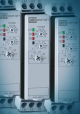
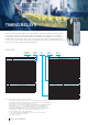
www.weg.net TIMING RELAYS Electronic devices that allow switching an output signal according to the timing range function and selected time. Designed according to international standards, they are available in 22.5 mm wide housings and can be mounted on DIN rails 35 mm or fixed with screws (PLMP accessory required) available with one or two NOC outputs.
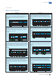
www.weg.net Time Range Adjustment Single Timing RTW - RE / PE / CI / CIR / CIL / CID / RD RTW - ET Red LED Output ON Time Y Green LED Supply voltage Time Δ RTW RE / PE / CIL / CID RD / CI / CIR RDI 0.1 - 1s1) 0.3 - 3s 0.3 - 3s 0.
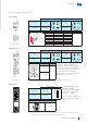
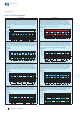
www.weg.net Functions Single Timing (RTW) or Multiple Timing (RTW-MAT/MBT) Relays Operating mode RTW RE (ON-delay) – After the relay is energized, the time (T) set on the dial begins. After the end of the delay time, the output contacts switch on and remain energized until the supply voltage is removed. RTW PE (impulse ON) – After the relay is energized, the output contacts switch on without delay and remain energized for the time (T) set on the dial.
www.weg.net Functions Multifunction Models (ERWT-MF1) Operating mode Operating mode A (ON-delay) – Timing begins when the supply voltage is applied. When the time delay (T) is completed, the output relay is energized. If the supply voltage is interrupted, the output relay is de-energized in case it is energized (after the time delay). If the relay supply voltage is interrupted before the time is completed, the time delay is reset and the output relay won’t be energized.
www.weg.net Functions Multifunction Models (ERWT-MF2) Operating mode Operating mode Cb (ON and OFF-delay with control signal) – Timing begins when the supply voltage is applied. When the selected time delay (T) is completed, the output relay is energized and/ or de-energized, depending on the current situation. If the supply voltage is interrupted, the output relay is de-energized in case it is energized (after the time delay).
www.weg.
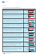
www.weg.net Specification Single Timing, Voltage and Function Relay Function: ON-Delay (RE) Model Function Contacts 1NOC RTW RE 2NOC Timing Reference (complete with the supply voltage) 0.1s - 1s RTW-RE01-U001S-" 0.3s - 3s 1s - 10s 3s - 30s 6s - 60s 10s - 100s 30s - 300s 3 - 30min 0.1s - 1s 0.
www.weg.net Specification Single Timing Relays Function: OFF-Delay (RDI) Model Function Contacts 1NOC RTW RDI 2NOC Timing Reference (complete with the supply voltage) 0.1s - 1s 0.3s - 3s 1s - 10s 3s - 30s 6s - 60s 10s - 100s 30s - 300s 1 - 10min 0.1s - 1s 0.
www.weg.net Specification Single Timing Relays Function: Flasher with One Setting and Start ON (CIL) Model Function Contacts 1NOC RTW CIL 2NOC Timing Reference (complete with the supply voltage) 0.1s - 1s RTW-CIL01-U001S-" 0.3s - 3s RTW-CIL01-U003S-" 1s - 10s RTW-CIL01-U010S-" 3s - 30s RTW-CIL01-U030S-" 6s - 60s RTW-CIL01-U060S-" 10s - 100s RTW-CIL01-U100S-" 30s - 300s RTW-CIL01-U300S-" 3 - 30min RTW-CIL01-U030M-" 0.1s - 1s RTW-CIL02-U001S-" 0.
www.weg.
www.weg.net Specification Multifunction Relays Models: MF1 / MF2 (Multifunction), Multiple Voltage and Multiple Timing Reference ERWT-MF1-02MT1E05 ERWT-MF2-02MT1E05 Supply voltage Contacts Timing 24-240 V ac/ V dc 2NOC 0.
www.weg.net Technical Data Rated supply voltage tolerance 110 to 130 V ac - - 50 / 60 Hz Maximum consumption Control supply voltage (RD function)2) 24 to 240 V ac / V dc 24 V dc 0.85 to 1.
www.weg.net Technical Data - - RTW-xx0X-UxxxD71 A3-A2 RTW-xxx0X-MxTE05 220 to 240 V ac RTW-RDI0X-UxxxE05 A1-A2 RTW-xxx0x-UxxxxC03 Supply voltage (Us)1) RTW-xxx0x-UxxxxD66 Model 24 V dc 24 to 240 V ac / V dc 24 to 240 V ac / V dc 380 to 440 V ac - - - Rated supply voltage tolerance 0.85 to 1.
www.weg.net Dimensions (mm) Single Timing or Multiple Timing Models 4 6 8 10s 2 1 8 10s 91.30 91,30 6 74.55 74,55 4 2 1 00 .8 4Ø,48 104,10 104.10 79,70 79.70 22.5 22,5 85.50 85,50 12,70 12.70 Multifunction Models (MF1 / MF2) 101.56 (3.999) 22.5 (0.886) 97.25 (3.829) 91.32 (3.595) 78.2 (3.079) 102.4 (4.032) 104.12 (4.099) Ø Ø4.8 (0.189) 12.5 (0.492) 106.05 (4.175) Accessories 27.6 16.3 5.
www.weg.net VOLTAGE MONITORS They are electronic devices intended to monitor three-phase systems and interrupt the process operation whenever a failure occurs. Designed according to international standards, they are available in 22.5 mm wide housings and can be mounted on DIN rails 35 mm or fixed with screws (PLMP accessory required), being a compact and safe solution. RPW-FF - Phase Loss Function It is intended to protect three-phase systems against the loss of one phase (without neutral).
www.weg.net RPW-SF - Phase Sequence Function It is intended to protect three-phase systems against the inversion of the phase sequence (L1-L2-L3). Installation It is directly connected to the three phases (terminals L1, L2 and L3) of the power grid to be monitored. Operation If the phase sequence is correct, the output relay switches the contacts to the operation position (closing terminals 15-18), and the red LED (relay) and green LED (power supply) will switch on.
www.weg.net RPW-FSF - Phase Loss and Phase Sequence Function It is intended to protect three-phase systems against phase loss and phase inversion. For applications with neutral, a bridge must be provided between terminals A and B. The RPW-FSF will monitor against phase loss and also the voltage on the neutral, which must be connected. Installation It is directly connected to the three phases (terminals L1, L2 and L3) of the power grid to be monitored (connect the neutral if applicable).
www.weg.net RPW-SS - Undervoltage and Overvoltage Function With this function, the RPW monitors the minimum and maximum voltage variations within which a three-phase power supply can operate. Whenever an under or overvoltage condition is present, the relay will switch its output in order to interrupt the operation of the monitored motor or process. Note: the RPW SS is suitable for line frequencies of 50/60 Hz.
www.weg.net RPW-PTC - Temperature Variation Monitoring via PTC Function It is intended to monitor the temperature variation in motors or generators in machines in general equipped with PTC temperature sensors. It has digital electronics, which provides high accuracy and noise immunity. Installation It must be connected in series to PTC sensors (maximum 3). The RPW has a test device for the PTC sensor. In case it is not connected or it is in a fault state, the LED will indicate (LED will flash).
www.weg.net ERWM-VM1 / VM2 The ERWM controls the faults in the voltage monitoring within which a three-phase supply voltage can operate. Whenever a failure in the power grid occurs, the relay will switch its output in order to interrupt the operation of the monitored motor or process. Installation It is directly connected to the three phases (L1, L2 and L3) of the power grid to be monitored (connect the neutral if applicable).
www.weg.net Functions Multiple Protection Models (ERWM-VM1 / VM2) Operating mode Operating mode PF (phase loss) – It occurs when the voltage of one of the phases drops below 70% of the supply voltage. The maximum time delay is 350 ms for both the fault detection and the return of the ERWM to normal operation. Timing diagram PS (phase sequence1) – It occurs when the phases are not connected in the correct sequence (L1-L2-L3) or even when a phase inversion occurs during operation.
www.weg.
www.weg.net Dimensions (mm) Single Timing or Multiple Timing Models 4 6 8 10s 2 1 8 10s 91.30 91,30 6 74.55 74,55 4 2 1 00 .8 4Ø,48 104,10 104.10 79,70 79.70 22.5 22,5 85.50 85,50 12,70 12.70 Multifunction Models (VM1 / VM2) 101.56 (3.999) 22.5 (0.886) 97.25 (3.829) 102.4 (4.032) 104.12 (4.099) 91.32 (3.595) ØØ4.8 (0.189) 106.05 (4.175) 12.5 (0.492) Accessories 27.6 16.3 PLMP Adapter 5.
www.weg.net LEVEL RELAY It is an electronic control device that enables monitoring and automatically setting the level of conductive (non-explosive) liquids by means of submerged electrodes. It has a dial that allows adjusting the electronic circuit to the liquid resistance.
www.weg.
www.weg.net Installation The electrodes must be installed on the RNW and fixed in the tank according to desired levels, minimum or maximum, and the reference electrode must be positioned in the lower part, below the other electrodes. The electrodes are available in 2 models, shaft (EHW) or pendulum (EPW). When a metallic tank is used, it can replace the reference electrode. Elet. max. Elet. max. Elet. min. Elet. min. Elet. C Elet.
www.weg.net Operation It is based on the measurement of the electric current of the liquid in the tank by means of a set of submerged electrodes, which work as liquid presence/absence sensors. When the system is energized, an alternating current1) is applied to the reference electrode. Once the liquid comes into contact with the electrodes, a path is established for the circulation of electric current between them.
www.weg.net Technical Data Product Supply voltage (1h) Inputs RNW ES / RNW EN A1-A2 Rated supply voltage tolerance 0.85 to 1.1 x Us Isolated rated voltage (Ui) 300 V Frequency 50/60 Hz Maximum consumption Contacts 2 / 1 VA/W 15 - 16 / 18 Capacity of the output contacts (Ie) 1 SPDT AC-12 (resistive) at 250 V ac - 5 A AC-15 at 230 V ac Outputs 100-240 V ac (50/60 Hz) / V dc 3A DC-13 at 24 V dc 1A DC-13 at 48 V dc 0.45 A DC-13 at 60 V dc 0.35 A DC-13 at 125 V dc 0.
www.weg.net Dimensions (mm) Model RNW-EN or RNW-ES 91.30 74.55 12.7 79.70 104.10 22.5 Ø4.80 85.50 Accessories Adapter for Screw Fixing 27.6 10 16.3 PLMP Adapter Adapter for Direct Mounting on WEG Contactors 5.50 22 MARC Adapter Note: the PLMP and MARC accessories can be used in any electronic relay (RTW, RPW or RNW).
www.weg.net Global presence is essential, as much as understanding your needs. Global Presence With more than 30.000 employees worldwide, WEG is one of the largest electric motors, electronic equipments and systems manufacturers. We are constantly expanding our portfolio of products and services with expertise and market knowledge. We create integrated and customized solutions ranging from innovative products to complete after-sales service.
WEG Worldwide Operations ARGENTINA San Francisco - Cordoba Phone: +54 3564 421484 info-ar@weg.net COLOMBIA San Cayetano - Bogota Phone: +57 1 4160166 info-co@weg.net MALAYSIA Shah Alam - Selangor Phone: +60 3 78591626 info@wattdrive.com.my SINGAPORE Singapore Phone: +65 68589081 info-sg@weg.net Cordoba - Cordoba Phone: +54 3514 641366 weg-morbe@weg.com.ar Sabaneta - Antioquia Phone: +57 4 4449277 info-co@weg.net Singapore Phone: +65 68622220 info-sg@weg.