
Information

www.weg.net
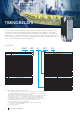
Timing Relays (RTW/ERWT)
10
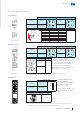
Multifunction Models (ERWT-MF2)
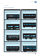
Operating mode
Cb (ON and OFF-delay with control signal) – Timing begins when the supply voltage is
applied. When the selected time delay (T) is completed, the output relay is energized and/
or de-energized, depending on the current situation. If the supply voltage is interrupted,
the output relay is de-energized in case it is energized (after the time delay). If the relay
supply voltage is interrupted before the time is completed, the time delay is reset and the
output relay won’t be energized. This function requires the continuous application of
supply voltage.
Timing diagram
Supply voltage
A1-A2
Output
15-18, 25-28
15-16, 25-26
Control voltage
B1-A2
LED U/T
LED R1
LED R2
T1
≥30ms
T1T2 <T1 T2<T2
Dd (symmetric flasher, start OFF) – Applying the supply voltage, timing begins with times
given by T1 (output ON) and T2 (output OFF). The cycle starts with the output relay de-
energized. The times of full scale range T1 and T2 are different. The total cycle is given by
T = T1+T2. Interrupting the supply voltage with the output energized resets the time delay
and de-energizes the output relay. This function requires the continuous application of
supply voltage.
Timing diagram
Supply voltage
A1-A2
Output
15-18, 25-28
15-16, 25-26
LED U/T
LED R1
LED R2
<T2T2 T1 T2 T1 T2 T1 T2 T1
Df (percentage flasher, start OFF – Applying the supply voltage, the output relay is
cyclically activated for a percentage of the cycle time (T). The time the output remains
activated is given by t = D.T, where D corresponds to the adjustment percentage
(0...100%). The cycle starts with the output relay de-energized. If the supply voltage is
interrupted before the time delay is completed with the output activated, the relay is de-
energized and the time delay is reset. This function requires the continuous application of
supply voltage.
Timing diagram
Supply voltage
A1-A2
Output
15-18, 25-28
15-16, 25-26
LED U/T
D=T1
T2
LED R1
LED R2
T1
T2
<T2
T2
T1
T2
T1
T1 > T2
Ia (delayed adjustable-length pulse) – The output relay is energized after the time T1 is
completed, and it remains activated while time T2 is applied. If the supply voltage is
interrupted before the time delay is completed, the relay is de-energized and the time
delay is reset, restarting the timing. This function requires the continuous application of
supply voltage.
Timing diagram
Supply voltage
A1-A2
Output
15-18, 25-28
15-16, 25-26
LED U/T
LED R1
LED R2
T1 T2 <T1 T1 <T2
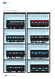
Operating mode
Dc (symmetric flasher, start ON) – Applying the supply voltage, timing begins with times
given by T1 (output ON) and T2 (output OFF). The cycle starts with the output relay
energized. The times of full scale range T1 and T2 are different. If the supply voltage is
interrupted before the time delay is completed, the relay is de-energized and the time
delay is reset. The total cycle is given by T = T1+T2. Interrupting the supply voltage with
the output energized resets the time delay and de-energizes the output relay. This function
requires the continuous application of supply voltage.
Timing diagram
Supply voltage
A1-A2
Output
15-18, 25-28
15-16, 25-26
LED U/T
LED R1
LED R2
T1 <T1T2 T1 T2 T1 T2 T1 T2
De (percentage flasher, start ON – Applying the supply voltage, the output relay is cyclically
activated for a percentage of the cycle time (T). The time the output remains activated is
given by t = D.T, where D corresponds to the adjustment percentage (0...100%). The cycle
starts with the output relay energized. If the supply voltage is interrupted before the time
delay is completed with the output activated, the relay is de-energized and the time delay
is reset. This function requires the continuous application of supply voltage.
Timing diagram
Supply voltage
A1-A2
Output
15-18, 25-28
15-16, 25-26
LED U/T
D=T1
T2
LED R1
LED R2
T1
T2
<T1
T2
T1
T2
T1
T1 > T2
Dg (flasher for motor reversing) – Applying the supply voltage, timing begins with times
given by T1 (output ON) and T2 (output OFF), toggling between the R1 and R2 relays each
time T1. The cycle begins with the output relay R1 energized and R2 de-energized. The
times of full scale range T1 and T2 are different. If the supply voltage is interrupted with
the output activated, the output relay R1 is energized, R2 is de-energized, and timing is
restarted by T1. This function requires the continuous application of supply voltage.
Timing diagram
Supply voltage
A1-A2
Output
25-28
25-26
LED U/T
LED R1
LED R2
Output
15-18
15-16
T1 <T1T2 T1 T2 T1 T2 T1 T2
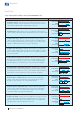
J (bistable) – The relay switches its output contacts between normally open (NO) and
normally closed (NC) and vice versa every pulse of the control signal. If the supply voltage
is interrupted with the output activated, the output relay is de-energized. This function is
not timed. This function requires the continuous application of supply voltage.
Timing diagram
Supply voltage
A1-A2
Output
15-18, 25-28
15-16, 25-26
Control voltage
B1-A2
LED U/T
LED R1
LED R2
≥30ms
Functions