
Datasheet

www.weg.net
C-19
C
B
D
A
MPW - Motor Protective Circuit Breakers
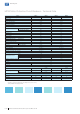
Shunt Release - SRMP
Mounting Configurations for MPW Motor Protective Circuit Breaker
Reference codes SRMP
For use with MPW12...40
Rated insulation voltage Ui 690 V
Operating voltage
(guarantee cir. breaker switch OFF)
0.7...1.1 x Ue
Energization consumption 20.2 VA / 13 W
Max. opening time 20 ms
Type of terminal Flat
Type of screws Phillips (Nº 2)
Tightening torque 1...1.5 N.m (7...10 lb.in)
Rigid cable
1 or 2 x (0.5...1.5 mm
2
)
1 or 2 x (0.75...2.5 mm
2
)
1 or 2 x (18...14 AWG)
Flexible cable
Backup fuses gL/gG 10 A
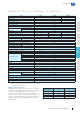
Live or grounded parts distance to the circuit breaker
Model Ue
Minimum distance between the circuit
breaker and live or grounded parts (mm)
B C A
MPW12...18 Up to 690 V 20 75 9
MPW40
Up to 500 V 30 95 9
Up to 690 V 50 95 30
The motor protective circuit breaker can be mounted in any position, but according to IEC 60447 standard, the “On - I” indicator must be to the right, or up.
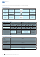
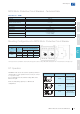
The MPW12...40 can also be used for operating continuous
current loads. For such operation it is necessary to connect
2 or 3 poles in series.
See recommended circuits and their voltage limits in the
table on the right.
Short-circuit breaking capacity Icu = 10 kA for all
configurations.
Circuits Max. V dc Notes
150 V dc
System not grounded;
2 pole series connected.
300 V dc
System grounded;
2 pole series connected.
450 V dc
System grounded;
3 pole series connected.
DC Operation
MPW Motor Protective Circuit Breakers - Technical Data