
Instructions


System overview | General description of the eld-bus coupler
10 1432790000/03/02.2014Manual u-remote
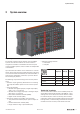
3.1 Generaldescriptionoftheeld-buscoupler
A eld-bus coupler is used to connect the station I/O mod-
ules to the eldbus. All of the data trafc with the program-
mable logic controller including the diagnostic messages is
exchanged via the coupler. The integrated power supply pro-
vides the coupler and all connected modules with power.
A detailed description of the individual coupler types is avail-
able in Chapter5.
1
3
2
4
5
6
4
12
10
11
9
8
7
14
13
13
15
16
18
17
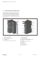
Field-buscoupler(example:UR20-FBC-PB-DP)
1 Catch lever for securing the DIN rail
2 Rotary switch (only Profibus)
3 Data line connection (e.g. SUB-D socket)
4 Seats for module markers
5 Type designation
6 Optional: swivel marker for labelling modules and channels
7 Connector frame unlocking device
8 LED power supply coupler
9 Fieldbus/coupler status LEDs
10 Power supply connector for the system and input modules
11 Power supply connector for output modules
12 Service flap
13 Latching hook for latching onto module sides
14 System bus
15 System current path
16 Input current path
17 Type plate with block diagram
18 Output current path