EG & PEG Series 5 EGH Series 5 Gas-Fired Boiler Manual EG PEG Boilers s )NSTALLATION s -AINTENANCE s 3TARTUP s 0ARTS For additional information, refer to . . . Control Supplement and Gas Control Parts for Natural or Propane gas (tankless heater application optional) EGH This manual must only be used by a qualified heating installer/service technician. "EFORE INSTALLING, read all instructions, including this manual, the burner manual and any related supplements. Perform steps in the order given.
EG & PEG SERIES 5 s EGH SERIES 5 GAS-FIRED BOILERS — BOILER MANUAL Hazard definitions The following defined terms are used throughout this manual to bring attention to the presence of hazards of various risk levels, or to important information concerning the life of the product. Indicates presence of hazards that will cause severe personal injury, death or substantial property damage.
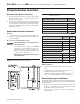
EG & PEG SERIES 5 s EGH SERIES 5 GAS-FIRED BOILERS — BOILER MANUAL Contents Codes and Checklist . . . . . . . . . . . . . . . . . . . . . . . . . . . . . . . . . . . . . . . . . 4 Prepare boiler location . . . . . . . . . . . . . . . . . . . . . . . . . . . . . . . . . . . . . . . 5 Prepare the boiler . . . . . . . . . . . . . . . . . . . . . . . . . . . . . . . . . . . . . . . . . . . 9 Connect piping — water boilers . . . . . . . . . . . . . . . . . . . . . . . . . . . . . .
EG & PEG SERIES 5 s EGH SERIES 5 GAS-FIRED BOILERS — BOILER MANUAL Codes & Checklist Installation must follow these codes: s s s s Local codes, laws, provincial and national codes, laws, regulations and ordinances .ATIONAL &UEL 'AS #ODE !.3) : LATEST EDITION 3TANDARD FOR #ONTROLS AND 3AFETY $EVICES FOR !UTOMATICALLY &IRED "OILERS !.3) !3-% CSD-1, when required .
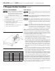
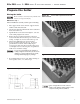
EG & PEG SERIES 5 s EGH SERIES 5 GAS-FIRED BOILERS — BOILER MANUAL Prepare boiler location Recommended Service clearances 4ABLE 1. Provide minimum clearances for cleaning and servicing the boiler and for access to controls and components as listed in the table at right. 2. Provide at least screwdriver clearance to jacket front panel screws for removal of front panel for inspection and minor service.
EG & PEG SERIES 5 s EGH SERIES 5 GAS-FIRED BOILERS — BOILER MANUAL 1 Prepare boiler location (continued) Flooring and foundation Vent System Do not install boiler on combustible flooring or carpeting even if a concrete or aerated foundation is used. Fire can result, causing severe personal injury, death or substantial property damage. 1. See Figure 2.
EG & PEG SERIES 5 s EGH SERIES 5 GAS-FIRED BOILERS — BOILER MANUAL Prepare boiler location Vent System (continued) Air contamination Chimney or vent requirements 6ENTING MUST BE INSTALLED ACCORDING TO THE .ATIONAL &UEL 'AS #ODE !.3) : nLATEST EDITION AND APPLICABLE BUILDING CODES #ANADIAN installations must comply with B149.1 or B149.2 Installation Codes. 2. See “Ratings” on page 38 for minimum chimney or vent sizes. Chimney or vent termination: 1.
EG & PEG SERIES 5 s EGH SERIES 5 GAS-FIRED BOILERS — BOILER MANUAL Prepare the location !IR OPENINGS Provide adequate combustion and ventilation air to assure proper combustion and reduce the risk of severe personal injury, death or substantial property damage caused by flue gas spillage and carbon monoxide emissions. Combustion air and ventilation openings must comply with THE .ATIONAL &UEL 'AS #ODE !.3) : n LATEST EDITION OR APplicable local building codes.
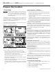
EG & PEG SERIES 5 s EGH SERIES 5 GAS-FIRED BOILERS — BOILER MANUAL Prepare the boiler Placing the boiler Block assembly is extremely heavy. Handle with caution to avoid personal injury. Figure 4a Corner after exposed silicone has been removed. EGH boilers only — When an EGH block assembly is taken apart for handling: 1. Put a support under center of block. Support must be within ½ inch of block bottom. 2. Detach seal replacement kit from the draw rod. Remove short center draw rods. 3.
EG & PEG SERIES 5 s EGH SERIES 5 GAS-FIRED BOILERS — BOILER MANUAL Prepare the boiler (continued) Hydrostatic pressure test Installation of optional indirect water heater 1. For a boiler ordered with internal type indirect water heater, REMOVE HEATER OPENING COVER PLATE WATER BOILERS n ROUND PLATE ON LEFT SIDE STEAM BOILERS n RECTANGULAR PLATE ON FRONT 2. Install heater(s) as shown on page 18. Do not over tighten studs and nuts - damage to the gasket can occur.
EG & PEG SERIES 5 s EGH SERIES 5 GAS-FIRED BOILERS — BOILER MANUAL Prepare the boiler (continued) Installation of flue collector hood (Factory installed on PEG boilers) Set flue collector hood on boiler as shown in Figure 6b. Use boiler cement furnished to provide gas-tight seal. Failure to maintain gas-tight seal can cause flue gas spillage and carbon monoxide emissions, resulting in severe personal injury or death. &IGURE B Flue collector hood Installation of side refractory -EGH only 1.
EG & PEG SERIES 5 s EGH 5 SERIES GAS-FIRED BOILERS — BOILER MANUAL Prepare the boiler (continued) &IGURE D EGH - Refractory placement & front base panel &IGURE C %' %'( Front base panel (Factory installed on PEG boilers) ( Q B Note! Silicone to be applied to inside of leg of cast surface.
EG & PEG SERIES 5 s EGH SERIES 5 GAS-FIRED BOILERS — BOILER MANUAL Prepare the boiler (continued) Installation of base shield - EGH only Draft hood installation 1. See Figure 8, slide base shield under burner drawer assembly. Attach draft hood to flue collector hood using #10 x 1/2” sheet metal screws provided. Use boiler cement furnished to provide gas tight seal. 2. The flanged end of the shield should be located at the front of the boiler.
EG & PEG SERIES 5 s EGH SERIES 5 GAS-FIRED BOILERS — BOILER MANUAL Connect piping – water boilers – EG only General Install the boiler jacket before connecting return piping. (Supply piping can be connected before or after jacket installation.) Connect controls after all piping is connected. If installation is to comply with ASME or Canadian requirements, an additional high temperature limit is needed. Install control in supply piping between boiler and isolation valve.
EG & PEG SERIES 5 s EGH SERIES 5 GAS-FIRED BOILERS — BOILER MANUAL Connect piping – water boilers – EG only (continued) $/ ./4 CONNECT DIRECTLY FROM WIRE ZONE VALVES TO THE 4 4 TERMINALS ON THE BOILER. When using 3-wire zone valves, install an isolation relay. Connect the zone valve end switch wires to the isolation relay coil. Connect the isolation relay contact across the boiler T-T terminals.
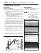
EG & PEG SERIES 5 s EGH SERIES 5 GAS-FIRED BOILERS — BOILER MANUAL Connect piping – water boilers – EG only &IGURE System bypass piping in boiler loop with separate system circulator, using primary/secondary piping. (continued) &IGURE Boiler bypass piping — use only for high water content systems —DO NOT use for radiant panel systems. System bypass method 1.
EG & PEG SERIES 5 s EGH SERIES 5 GAS-FIRED BOILERS — BOILER MANUAL Connect piping – steam boilers (continued) General &IGURE Recommended piping for parallel-flow systems Failure to properly pipe the boiler may result in improper operation and damage to the boiler or building. 1. 2. 3. 4. Steam supply must be on same end as controls. Return may be from either end. Install the boiler jacket before connecting return piping. (Supply piping can be connected before or after jacket installation.
EG & PEG SERIES 5 s EGH SERIES 5 GAS-FIRED BOILERS — BOILER MANUAL Connect piping – steam boilers (continued) &IGURE Connection to counterflow steam piping Installing the relief valve Install relief valve in tapping on top of boiler. See Table 4, page 10, for control tapping locations. See the tag attached to the relief valve for manufacturer’s instructions. Follow the steps below to avoid potential severe personal injury, death or substantial property damage.
EG & PEG SERIES 5 s EGH 5 SERIES GAS-FIRED BOILERS — BOILER MANUAL Connect piping – steam boilers (continued) Condensate return &IGURE Recommended piping for parallel-flow systems with optional reservoir pipe Modern steam boilers are designed to steam for less time than older, larger boilers. When replacing an older steam boiler the system condensate return time may be longer than the steaming time. This could cause the following problems: 1.
EG & PEG SERIES 5 s EGH SERIES 5 GAS-FIRED BOILERS — BOILER MANUAL Install boiler controls Failure to properly install, pipe and wire boiler controls may result in severe damage to the boiler, building and personnel. &IGURE Probe-type low water cut-off Water boiler - EG only 1. Install controls as shown on Control Tapping Table and Figure 5, page 10. 2. Low water cut off for water boilers: a) Must be installed if boiler is located above radiation level.
EG & PEG SERIES 5 s EGH SERIES 5 GAS-FIRED BOILERS — BOILER MANUAL Connect piping – tankless heater (optional) EG and EGH boilers for tankless heater application are available only on special order as factoryinstalled optional equipment. Standard boilers cannot be adapted for heater use. Install a tankless heater only in a steam boiler or forced hot water. For correct operation, install as shown in Figure 24 (water boilers) or Figure 25 (steam boilers). 1.
EG & PEG SERIES 5 s EGH SERIES 5 GAS-FIRED BOILERS — BOILER MANUAL Connect gas supply piping 6. Pipe joint compound (pipe dope) must be resistant to corrosive action of liquefied petroleum gases. Apply sparingly only to make threads of pipe joints. Connecting gas supply piping 1. Size gas piping considering: a) Diameter and length of gas supplying piping. b) Number of fittings. c) Maximum gas consumption (including any possible future expansion).
EG & PEG SERIES 5 s EGH SERIES 5 GAS-FIRED BOILERS — BOILER MANUAL For your safety, turn off electrical power supply at service entrance panel before making any electrical connections to avoid possible electric shock hazard. Failure to do so can cause severe personal injury or death. Refer to the Control Supplement for additional information, operating instructions and control wiring diagram. Wiring must be N.E.C. Class 1.
EG & PEG SERIES 5 s EGH SERIES 5 GAS-FIRED BOILERS — BOILER MANUAL Start-up Wiring multiple zones Refer to zone valve manufacturer’s literature for wiring and application. A separate transformer is required to POWER ZONE VALVES :ONING WITH CIRCULATORS REQUIRES A relay for each circulator. $/ ./4 CONNECT DIRECTLY FROM WIRE ZONE VALVES TO THE 4 4 TERMINALS ON THE BOILER. When using 3-wire zone valves, install an isolation relay. Connect the zone valve end switch wires to the isolation relay coil.
EG & PEG SERIES 5 s EGH SERIES 5 GAS-FIRED BOILERS — BOILER MANUAL Start-up (continued) Skim the steam boiler Clean all newly installed steam boilers to remove oil and grease. Failure to properly clean can result in violent fluctuations of water level, water passing into steam mains or high maintenance costs on strainers, traps and vents. Do not use petroleum-based cleaning or sealing compounds in boiler system. Severe damage to boiler will occur, resulting in substantial property damage. 1.
EG & PEG SERIES 5 s EGH SERIES 5 GAS-FIRED BOILERS — BOILER MANUAL Start-up (continued) If boiler doesn’t start . . . Check for: 1. Loose connections, blown fuse or service switch off? 2. High limit switch set below boiler pressure? 3. Thermostat set below room temperature? 4. Gas not turned on at meter or boiler? 5. Incoming gas pressure less than: 5” w.c. for natural gas? 11” w.c. for propane gas? 6. If none of the above corrects the problem, see “Troubleshooting” in the Control Supplement.
EG & PEG SERIES 5 s EGH SERIES 5 GAS-FIRED BOILERS — BOILER MANUAL Start-up (continued) ❏ Check-out procedure Check-off steps as completed. ❏ System properly filled with water? ❏ ❏ Automatic air vent, if used, open one turn (water boilers only)? ❏ Air purged from system (water boilers only)? ❏ Steam boilers properly skimmed? ❏ ❏ Air purged from gas piping? Piping checked for leaks? ❏ ❏ Are proper orifices installed? Check page 11 for proper size. Proper orifices must be used.
EG & PEG SERIES 5 s EGH SERIES 5 GAS-FIRED BOILERS — BOILER MANUAL Department of Energy – Compliance EG water boilers only This boiler is equipped with a control system that automatically adjusts a time delay period to turn on the boiler during a call for heat. This is accomplished by circulating available hot water in the system while measuring water boiler water temperature changes.
EG & PEG SERIES 5 s EGH SERIES 5 GAS-FIRED BOILERS — BOILER MANUAL Service and maintenance 4ABLE 3ERVICE AND MAINTENANCE SCHEDULES SERVICE TECHNICIAN AND OWNER Service technician Owner maintenance (see following pages for instructions) (see User’s Information Manual for instructions) Daily s Check boiler area Inspect: s Check air openings s Reported problems s Check boiler pressure/ s Boiler area temperature gauge s Air openings s Flue gas vent system Monthly s Check boiler interio
EG & PEG SERIES 5 s EGH SERIES 5 GAS-FIRED BOILERS — BOILER MANUAL Service and maintenance (continued) The boiler should be inspected and started annually, at the beginning of the heating season, only by a qualified service technician. In addition, the maintenance and care of the boiler designated in Table 12, page 29 and explained on the following pages must be performed to assure maximum boiler efficiency and reliability.
EG & PEG SERIES 5 s EGH SERIES 5 GAS-FIRED BOILERS — BOILER MANUAL Service and maintenance (continued) ❏ 3ERVICE Probe-type low water cutoff (when used) Gauge glass (steam boilers) 1. 2. 3. 4. 5. Normal waterline is halfway up gauge glass. Clean when needed. Close lower gauge cock. Open pet cock. Open lower gauge cock and allow a small amount of water to flush out through open pet cock. Close pet cock. Open lower gauge cock. Temperature sensor 1.
EG & PEG SERIES 5 s EGH SERIES 5 GAS-FIRED BOILERS — BOILER MANUAL Service and maintenance (continued) ❏ #HECK TEST Boiler relief valve 1. After following the warning directions below, if the relief valve weeps or will not seat properly, replace the relief valve. Before testing, make certain discharge pipe is properly connected to valve outlet and arranged to contain and safely dispose of boiler discharge.
EG & PEG SERIES 5 s EGH SERIES 5 GAS-FIRED BOILERS — BOILER MANUAL REMOVAL OF COMBUSTION CHAMBER LINING OR BASE PANELS The combustion chamber lining or base insulation panels in this product contain ceramic fiber materials. Ceramic fibers can be converted to cristobalite in very high temperature applications.
EG & PEG SERIES 5 s EGH SERIES 5 GAS-FIRED BOILERS — BOILER MANUAL Replacement parts — EG/PEG 4ABLE Item A B C D E EG/PEG replacement parts Description : : { Boiler Models * B @y@Q * B @y@K * B @y@@y –– –– –– –– ^ * B @y@X Draft hood F & & F1 & & , G M
EG & PEG SERIES 5 s EGH SERIES 5 GAS-FIRED BOILERS — BOILER MANUAL Replacement parts — EG/PEG (continued) The boiler contains ceramic fiber and fiberglass materials. Use care when handling these materials per instructions on page 33 of this manual. Failure to comply could result in severe personal injury.
EG & PEG SERIES 5 s EGH SERIES 5 GAS-FIRED BOILERS — BOILER MANUAL Replacement parts — EGH 4ABLE Item A EGH replacement parts Description Boiler Models : * B @y@Q : * B @y@K B –– { * B @y@\ –– { * B @y@@y C C1 –– –– ^ * B @y@X ^
EG & PEG 5 s EGH SERIES SERIES 5 GAS-FIRED BOILERS — BOILER MANUAL Replacement parts — EGH (continued) The boiler contains ceramic fiber and fiberglass materials. Use care when handling these materials per instructions on page 33 of this manual. Failure to comply could result in severe personal injury.
EG & PEG SERIES 5 s EGH SERIES 5 GAS-FIRED BOILERS — BOILER MANUAL Dimensional data 4ABLE Dimensional data Gas Connection “F” Dimensions Draft hood outlet size Approx. ship. wt.
EG & PEG SERIES 5 s EGH SERIES 5 GAS-FIRED BOILERS — BOILER MANUAL Ratings 4ABLE Ratings DOE Boiler Model Number 0–2,000 feet altitude Input DOE Heating Capacity Gross Output * @ *EG-30*EG-35*EG-40*EG-45*EG-50*EG-55*EG-65- 2,000–4,500 feet altitude (Canada) Input * I (Output) Net AHRI Ratings Sq. Ft.
EG & PEG SERIES 5 s EGH SERIES 5 GAS-FIRED BOILERS — BOILER MANUAL Standard and optional equipment Standard equipment EG additional equipment s s s s s s s s s Factory-Assembled Section Block Insulated Extended Jacket Draft Hood Aluminized Steel Burners Non-Linting Pilot Burner Heater Cover Plates (for boilers with tankless heater openings) Control Wire Electrical Junction Box s EGH boilers add: EG/PEG boilers add: s s s s s s s #OMBINATION 'AS 6ALVE FOR VOLT Thermocouple (high efficien