CGa Series 2, CGi Series 3, EG Series 5, EGH Series 5, LGB Series 2, PEG Series 5 Gas-Fired Boilers User’s Information Manual INSTALLER: Please take time to review this User’s information Manual with the boiler owner. Explain all maintenance and service procedures and the correct Operating Instructions. If the information in this manual is not followed exactly, a fire or explosion may result, causing property damage, personal injury or loss of life.
CGa, CGi, EG, EGH, LGB, PEG, Boilers Please read this page first How to use this manual . . . Hazard definitions To . . . Read/Use . . . Pages . . . Learn precautions Warnings and definitions Prevent air contamination Read list of air contaminants you must avoid. If found, either remove products permanently or isolate boiler and provide outside combustion air. 3 Identify boiler components The illustration on page 4 or 5, will show you the location of the main components.
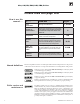
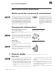
User’s Information Manual STOP!! — Read before proceeding Failure to adhere to the guidelines on this page can result in severe personal injury, death or substantial property damage. Air contamination • • • To prevent potential of severe personal injury or death, check for products or areas listed in table at right before installing boiler. If any of these contaminants are found: remove contaminants permanently. — OR — isolate boiler and provide outside combustion air.
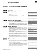
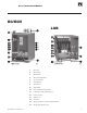
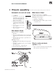
CGa, CGi, EG, EGH, LGB, PEG, Boilers Boiler components CGa CGi 1 2 3 4 5 6 7 8 9 10 11 12 15 16 17 18 19 4 Gas valve Pilot burner Main burner Gas manifold/orifices Control module Inducer (CGi only) Vent damper (CGa only) Water temperature sensor Transformer Spill switch (CGa only) Air pressure switch (CGi only) Rollout thermal fuse element Draft hood (CGa only) Circulator Relief valve Gauge (pressure or pressure/temperature) Timer relay (CGi-4 only) Part Number 550-142-801/1112
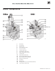
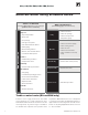
User’s Information Manual EG/EGH LGB Part Number 550-142-801/1112 1 Gas valve 2 Pilot burner 3 Main burner 4 Gas manifold/orifices 5 Control module 7 Vent damper 9 Transformer 10 Spill switch 12 Rollout thermal fuse element 13 Low water cutoff (steam boilers) 14 Limit control(s) 15 Draft hood 16 Circulator 18 Gauge (pressure or pressure/temperature) 19 Gauge glass (steam only) 5
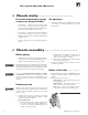
CGa, CGi, EG, EGH, LGB, PEG, Boilers Maintain boiler using schedule below Service technician Owner maintenance (covered in Boiler Manual – for use only by a qualified service technician) (see following pages for instructions) • Check boiler area Inspect: Daily • Reported problems • Boiler area • Check air openings • Check boiler pressure/ temperature gauge • Air openings • Flue gas vent system • Check boiler interior piping • Pilot and main burner flames • Check venting system • Water piping Mon
User’s Information Manual User maintenance procedures Boiler must be serviced & maintained The boiler should be inspected and started annually, at the beginning of the heating season, only by a qualified service technician. In addition, the maintenance and care of the boiler designated on page 6 and explained on the following pages must be performed to assure maximum boiler efficiency and reliability.
CGa, CGi, EG, EGH, LGB, PEG, Boilers ❏ Check daily . . . . . . . . . . . . . . . . . Pressure/temperature gauge or pressure gauge (steam) 1. Water boilers — Make sure the pressure reading on the boiler pressure/temperature gauge does not exceed 24 psig. Higher pressure may indicate a problem with the expansion tank or gauge. Air openings 1. Verify that combustion and ventilation air openings to the boiler room and/or building are open and unobstructed. 2.
User’s Information Manual ❏ Check monthly . . . . . . . . . . . . . . . . Automatic air vents (if used) 1. See Figure 4. 2. Remove the cap from any automatic air vent in the system and check operation by depressing valve B slightly with the tip of a screwdriver. 3. If the air vent valve appears to be working freely and not leaking, replace cap A, twisting all the way on. 4. Loosen cap A one turn to allow vent to operate. 5. Have vent replaced if it does not operate correctly.
CGa, CGi, EG, EGH, LGB, PEG, Boilers ❏ Service periodically . . . . . . . . . . . . Test low water cutoff (all steam boilers) (water boilers, if installed) If the system is equipped with a low water cutoff, test the low water cutoff periodically during the heating season. Float type — See Figure 7 Probe type— See Figure 8 1. Clean float type low water cutoff to clear float chamber of sediment. 1. Clean probe type low water cutoff for proper operation. a. Open blowdown valve at bottom control. b.
User’s Information Manual ❏ Service periodically continued . ...... Clean gauge glass Normal waterline on a steam boiler is halfway up gauge glass. See Figure 9. Clean when needed. 1. Close lower gauge cock. 2. Open pet cock. 3. Open lower gauge cock and allow a small amount of water to flush out through open pet cock. 4. Close pet cock. 5. Open lower gauge cock. 6. If gauge glass breaks, close both gauge cocks and call a qualified service technician to replace gauge glass.
CGa, CGi, EG, EGH, LGB, PEG, Boilers ❏ End-of-season shutdown . . . . . . . . Follow boiler shutdown procedure 1. Follow “TO TURN OFF GAS TO APPLIANCE” on the Operating instructions on the inside of the jacket panel. You will also find these instructions on pages 13 through 19 of this manual. Use the Operating instruction for the gas valve model installed on the boiler. 2. Do not drain system unless exposure to freezing temperatures will occur. 3.
User’s Information Manual Operating instructions CGa, EG-30 to EG-75, PEG-30 to PEG-55, • Spark-ignited pilot • Gas valve — Honeywell VR8204/VR8304 FOR YOUR SAFETY READ BEFORE OPERATING If you do not follow these instructions exactly, a fire or explosion may result causing property damage, personal injury or loss of life. A. This appliance is equipped with an ignition device which automatically lights the pilot. Do not try to light the pilot by hand. B.
CGa, CGi, EG, EGH, LGB, PEG, Boilers Operating instructions CGa-25 to CGa-6, EG-30 to EG-50, PEG-30 to PEG-50 • Spark-ignited pilot • Gas valve — White-Rodgers 36E FOR YOUR SAFETY READ BEFORE OPERATING If you do not follow these instructions exactly, a fire or explosion may result causing property damage, personal injury or loss of life. A. This appliance is equipped with an ignition device which automatically lights the pilot. Do not try to light the pilot by hand. B.
User’s Information Manual Operating instructions CGa-7, CGa-8, EG-55 to EG-75, PEG-55, • Spark-ignited pilot • Gas valve — White-Rodgers 36C FOR YOUR SAFETY READ BEFORE OPERATING If you do not follow these instructions exactly, a fire or explosion may result causing property damage, personal injury or loss of life. A. This appliance is equipped with an ignition device which automatically lights the pilot. Do not try to light the pilot by hand. B.
CGa, CGi, EG, EGH, LGB, PEG, Boilers Operating instructions • Spark-ignited pilot • Gas valve — Robertshaw 7200 16 CGa-25 to CGa-6, EG-30 to EG-50, PEG-30 to PEG-50 Part Number 550-142-801/1112
User’s Information Manual Operating instructions EGH-85 to EGH-125, • Spark-ignited pilot • Gas valve — Robertshaw 7000DERHC Part Number 550-142-801/1112 17
CGa, CGi, EG, EGH, LGB, PEG, Boilers Operating instructions CGi • Spark-ignited pilot • Gas valve — Honeywell VR8204/VR8304, White-Rodgers 36C and 36E FOR YOUR SAFETY READ BEFORE OPERATING If you do not follow these instructions exactly, a fire or explosion may result causing property damage, personal injury or loss of life. A. This appliance does not have a pilot. It is equipped with an ignition device which automatically lights the burner. Do not try to light the burner by hand. C.
User’s Information Manual Operating instructions LGB • Spark-ignited pilot Part Number 550-142-801/1112 19
Common problems and solutions Symptom Common Causes Possible Corrections Rapid cycling — boiler turns on and off frequently Thermostat installed where drafts or heat affect reading Locate thermostat on inner wall away from heat sources or cool drafts. Heat anticipator in thermostat adjusted incorrectly Adjust thermostat per manufacturer's instructions. Incorrect limit setting Set limit according to system needs. Maximum setting is 220°F. Increase limit setting to decrease cycling.