
User Guide


User’s Information Manual
9
Part Number 550-142-801/1112
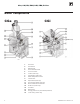
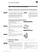
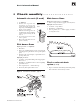
Figure 4
Automatic air
vent
Automatic air vents (if used)
1. See Figure 4.
2. Remove the cap from any
automatic air vent in the
system and check operation by
depressing valve B slightly with
the tip of a screwdriver.
3. If the air vent valve appears to be
working freely and not leaking,
replace cap
A, twisting all the
way on.
4. Loosen cap A one turn to allow
vent to operate.
5. Have vent replaced if it does not
operate correctly.
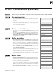
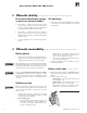
Pilot burner flame
Proper pilot flame (see Figure 5):
1. Blue flame.
2. Inner cone engulfing thermocouple or thermopile
(standing pilot) or pilot flame sensor (spark-ignited
pilot).
3. Thermocouple or thermopile, or pilot flame sensor
glowing cherry red.
Improper pilot flame:
1. Overfired — Large flame lifting or blowing past pilot
flame sensor.
2. Underfired — Small flame. Inner cone not engulfing
pilot flame sensor.
3. Lack of primary air — Yellow flame tip.
4. Incorrectly heated pilot flame sensor.
Main burner flame
Proper main burner flame (see Figure 6):
1. Yellow-orange streaks may appear (caused by dust).
Improper main burner flame:
1. Overfired — Large flames.
2. Underfired — Small flames.
3. Lack of primary air — Yellow tipping on flames
(sooting will occur).
Figure 5 Pilot burner and flame, typical
Figure 6 Main burner flame, typical
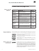
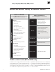
❏ Check monthly . . . . . . . . . . . . . . . .
Check condensate drain
system (if used)
1. Inspect condensate drain fittings and tubing. Verify
that condensate can flow freely to drain.