LGB Series 2 Gas–Fired Boiler Boiler Manual s )NSTALLATION s -AINTENANCE s 3TART UP s 0ARTS Refer to Control Supplement for additional information Read all instructions before installing Installer Owner Leave all instructions with boiler for future reference. Any claims for damage or shortage in shipment must be filed immediately against the transportation company by the consignee. Installation and service should be performed by qualified contractor. Part No.
LGB 3ERIES 'AS &IRED "OILER "OILER -ANUAL Hazard The following defined terms are used throughout this manual to bring attention to the presence of hazards of various risk levels, or to important information concerning the life of the product. Indicates presence of hazards that will cause severe personal injury, death or substantial property damage. Indicates presence of hazards that can cause severe personal injury, death or substantial property damage.
s )NSTALLATION s 3TART 5P s -AINTENANCE s 0ARTS Contents 1 2 3 4 5 6 7 8 9 10 11 12 13 14 Part Number 550-141-186/0914 Codes.......................................................................................... 4 Air openings ............................................................................... 4 Venting ....................................................................................... 6 Foundation ......................................................................
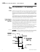
LGB 3ERIES 'AS &IRED "OILER "OILER -ANUAL 1a ! Pre-installation — air openings )NSTALLATIONS MUST COMPLY WITH ALL LOCAL CODES LAWS REGULATIONS AND ORDINANCES ALSO .ATIONAL &UEL 'AS #ODE !.3) : nLATEST EDITION 7HEN REQUIRED INSTALLATIONS MUST CONFORM TO 3TANDARD FOR #ONTROLS AND 3AFETY $EVICES FOR !UTOMATICALLY &IRED "OILERS !.
s )NSTALLATION s 3TART 5P s -AINTENANCE s 0ARTS ! ) (continued) s s 4IGHTLY CONSTRUCTED BUILDINGS MUST BE PROVIDED WITH OPENINGS TO OUTSIDE FOR COMBUSTION and ventilation air. These openings must be sized to handle all fuel-burning appliances, exhaust and ventilation fans and fireplaces.
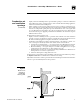
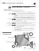
LGB 3ERIES 'AS &IRED "OILER "OILER -ANUAL 1b ! , Pre-installation — venting 6ENTING MUST BE INSTALLED ACCORDING TO 0ART 6ENTING OF %QUIPMENT OF .ATIONAL &UEL 'AS #ODE !.3) : nLATEST EDITION AND APPLICABLE BUILDING CODES #ANADIAN INSTALLATIONS MUST COMPLY WITH #!. #3! " OR " )NSTALLATION #ODE Breeching must not be connected to any portion of mechanical draft system that can operate under positive pressure.
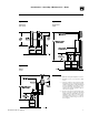
s )NSTALLATION s 3TART 5P s -AINTENANCE s 0ARTS - / Individual stub vents Combined vents 0 Offset vents Notes Part Number 550-141-186/0914 -INIMUM VENT HEIGHT USING FULL SIZE CONNECTOR 2. -INIMUM FEET ABOVE ANY STRUCTURE WITHIN FEET 3. Vent and combined vent materials, length and diameter must be determined using the COMBINED VENTING TABLES OF THE .ATIONAL &UEL 'AS #ODE !.3) : nLATEST EDITION OR OTHER accepted engineering design method.
LGB 3ERIES 'AS &IRED "OILER "OILER -ANUAL 1c 2 Flammable materials Pre-installation — foundation Consider all connections to the boiler before selecting a location. Boiler must be installed so gas control system components are protected from dripping or spraying water or rain during operation or service.
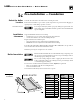
s )NSTALLATION s 3TART 5P s -AINTENANCE s 0ARTS 2a Boiler assembly — base The boiler contains ceramic fiber and fiberglass materials. Use care when handling these materials per instructions on page 28 of this manual. Failure to comply could result in severe personal injury. Check for proper orifice size: s .ATURAL GAS n MM s 0ROPANE GAS n MM Proper orifices must be used. Failure to do so will cause severe personal injury, death or substantial property damage.
LGB 3ERIES 'AS &IRED "OILER "OILER -ANUAL 2b 2 Boiler assembly — sections Assembly may start at either end section. For easier assembly start with right end section. 0OSITION RIGHT END SECTION mUSH WITH RIGHT END OF BASE 3EE Figure 13 ON PAGE Sections are top-heavy Do not precut rope Sections are top heavy and will not stand individually without support. Severe personal injury, death or substantial property damage can result. 2.
s )NSTALLATION s 3TART 5P s -AINTENANCE s 0ARTS 2 (continued) 8. Place all sections on base assembly insuring sections are straight and properly aligned with alignment lugs. Snug the lower front and rear draw rods on every section. Do not tighten front upper draw rods. Front upper draw rods must remain loose until LOWER FRONT AND REAR DRAW RODS ARE TIGHTENED TO PROPER TORQUE 3EE Figure 10. a. Oil threads on all draw rods. Install washer and nut on end to be tightened.
LGB 3ERIES 'AS &IRED "OILER "OILER -ANUAL Boiler assembly — pressure test 2c 7 Pressure test before connecting gas piping and electrical supply. Refer to Figures 11a and 11b for control tapping locations. Install: a. Boiler drain (not supplied). b. Water pressure gauge — for test only. Be sure gauge can handle test pressures. See Step 3. 2. Plug remaining tappings. DO NOT pressure test with any controls installed. Damage to control can No controls installed occur.
s )NSTALLATION s 3TART 5P s -AINTENANCE s 0ARTS 7 4. Check for maintained gauge pressure and leaks. Repair if found. 5. Drain boiler and remove plugs from tappings used for controls and accessories. (continued) Repair leaks at once Leaks must be repaired at once. Failure to do so can damage boiler, resulting in substantial property damage. No petroleumbased chemicals Do not use petroleum-based cleaning or sealing compounds in boiler system.
LGB 3ERIES 'AS &IRED "OILER "OILER -ANUAL 2d Boiler assembly — cleanout plates The boiler contains ceramic fiber and fiberglass materials. Use care when handling these materials per instructions on page 28 of this manual. Failure to comply could result in severe personal injury. ! Gas-tight seal Assemble cleanout plates to section assembly as shown in Figure 12.
s )NSTALLATION s 3TART 5P s -AINTENANCE s 0ARTS 2e See Figure 13 — single base shown. Refer to the table below, for proper arrangement. !SSEMBLE BOLT WASHER AND NUT TO SECTION JOINT 2. Apply retort cement for gas-tight seal. Gas-tight seal Hood must be sealed gas-tight to prevent possibility of flue gas spillage and carbon monoxide emissions, causing severe personal injury or death.
LGB 3ERIES 'AS &IRED "OILER "OILER -ANUAL 3a Piping — water boilers Improper piping systems and/or undersized piping can contribute to erratic boiler operation and possible boiler damage. Install piping as shown below. LGB-4 through LGB-12 only — supply and return piping can be on same end. )NSTALL SYSTEM SUPPLY AND RETURN PIPING BEFORE ERECTING JACKET OR INSTALLing controls. 2. Do not pipe in through supply and out through return.
s )NSTALLATION s 3TART 5P s -AINTENANCE s 0ARTS ; (systems above 140°F) 7EIL -C,AIN RECOMMENDS PIPING as shown in Figure 15. For single boilers, pipe as shown for one unit. 1 3IZE SECONDARY BOILER PUMP '0FOR & TO & TEMPERATURE RISE through boiler. Secondary boiler pump head will be very low. Calculate only secondary piping circuit resistance. Boiler resistance will not exceed 6” w.c. 2 0RIMARY PUMP '0- AND HEAD calculation should not include secondary boiler circuits.
LGB 3ERIES 'AS &IRED "OILER "OILER -ANUAL 3b Piping — steam boilers Improper piping systems and/or undersized piping can contribute to erratic boiler operation and possible boiler damage. The piping must be installed as illustrated, using the recommended minimum pipe sizes. Pipe the header at least 24 inches above the boiler water line.
s )NSTALLATION s 3TART 5P s -AINTENANCE s 0ARTS ! ) 3ATISFACTORY OPERATION OF ANY STEAM HEATING SYSTEM DEPENDS UPON ADEQUATE return of condensate to maintain steady water level. Avoid adding excessive AMOUNT OF RAW MAKEUP WATER 7HERE CONDENSATE RETURN IS NOT ADEQUATE A low water cutoff and pump control, condensate receiver, and condensate boiler feed pump should be installed. Refer to Figure 19 for piping and condensate receiver capacity table for sizing.
LGB 3ERIES 'AS &IRED "OILER "OILER -ANUAL 3c Piping — multiple steam boilers +6 Piping multiple steam boilers : 1 %ACH BOILER HAS A BOILER FEED PUMP CONTROLLER NOT SHOWN ,EVEL CONTROLS 3ECTION MUST BE MOUNTED ON SAME SIDE OF BOILER AS RETURN 2 -OUNT EACH BOILER FEED PUMP CONTROLLER WITH BODY MARK AT THE LEVEL INDICATED IN 4ABLE PAGE AND &IGURE PAGE 3 4 ,OCATE SYSTEM STEAM SUPPLY TAKEOFF OUTBOARD FROM THE BOILER CONNECTING PIPING AS SHOWN TO ASSURE LIQUID IN LINE WIL
s )NSTALLATION s 3TART 5P s -AINTENANCE s 0ARTS 4 Jacket The boiler contains ceramic fiber and fiberglass materials. Use care when handling these materials per instructions on page 28 of this manual. Failure to comply could result in severe personal injury. # 5 < Refer to separate LGB Jacket erecting instructions packed in Jacket Carton.
LGB 3ERIES 'AS &IRED "OILER "OILER -ANUAL 6 Install boiler controls Failure to properly install, pipe and wire boiler controls may result in severe damage to the boiler, building and personnel. Controls Relief valve stem vertical only ( Install relief valve with spindle in vertical position. Relief valve discharge piping must be piped near floor close to floor drain to eliminate potential of severe burns. Do not pipe to any area where freezing could occur.
s )NSTALLATION s 3TART 5P s -AINTENANCE s 0ARTS ++ 1 .IPPLE v X v Steam boiler control installation 2 5NION v 3 .IPPLE v X v 4 #ROSS v 5 .IPPLE v X v 6 .IPPLE v X v USED ONLY WITH -ODEL LWCO CUT TO lT for other controls) 7 0LUG v 8 .IPPLE v X v NOT INCLUDED 9 .
LGB 3ERIES 'AS &IRED "OILER "OILER -ANUAL 7a Final Adjustments — water boilers ( Do not use petroleum-based cleaning or sealing compounds in boiler system. Severe boiler damage will occur. #ONTINUAL FRESH MAKEUP WATER WILL REDUCE BOILER LIFE -INERALS CAN BUILD UP IN SECTIONS REDUCing heat transfer, overheating cast iron, and causing section failure.
s )NSTALLATION s 3TART 5P s -AINTENANCE s 0ARTS 7b Final Adjustments — steam boilers ( Do not use petroleum-based cleaning or sealing compounds in boiler system. Severe boiler damage will occur. #ONTINUAL FRESH MAKEUP WATER WILL REDUCE BOILER LIFE -INERALS CAN BUILD UP IN SECTIONS REDUCing heat transfer, overheating cast iron, and causing section failure. )N HARD WATER AREAS OR LOW P( CONDITIONS BELOW CONSULT LOCAL WATER TREATMENT COMPANY 2. 4.
LGB 3ERIES 'AS &IRED "OILER "OILER -ANUAL 8 8 Before lighting pilot Placing boiler in operation 4URN OPERATING CONTROL TO OFF position or lowest position on dial. Be sure boiler has been correctly filled with water. 2. Turn OFF electric power. -AIN SHUTOFF GAS VALVE MUST BE CLOSED FOR AT LEAST lVE MINUTES BEFORE lighting to prevent minor personal injury or property damage. 3. Open manual main gas valve. 4. Adjust operating control to provide call for heat.
s )NSTALLATION s 3TART 5P s -AINTENANCE s 0ARTS 9 Check-out procedure — check off steps as completed 2. 3. 4. 5. 6. 3YSTEM PROPERLY lLLED WITH WATER Automatic air vent, if used, open one turn (water boilers only)? Air purged from system (water boilers only)? Steam boilers properly skimmed? Air purged from gas piping? Piping checked for leaks? Are proper orifices installed? See Control Supplements for orifice sizes. Proper orifices must be used.
LGB 3ERIES 'AS &IRED "OILER "OILER -ANUAL 10a Also refer to additional instructions shipped with boiler for specific control operation and troubleshooting. (AVE YOUR BOILER INSPECTED CLEANED AND IF NECESSARY ADJUSTED ONCE A YEAR BY A QUALIlED service agency. To avoid severe personal injury, death or substantial property damage — before servicing: $ISCONNECT ELECTRICAL SUPPLY 2. Shut off gas supply. 3. Allow boiler to cool.
s )NSTALLATION s 3TART 5P s -AINTENANCE s 0ARTS 10b Maintenance — minimum schedule !NNUAL SERVICE CALL BY A QUALIlED SERVICE AGENCY 2. Check burners and flueways and clean if necessary. Refer to Clean boiler heating surfaces and Clean main burners, Section 10c PAGE 3. Follow procedure, Section 8, Placing boiler in operation, page 26. 4. Visually inspect pilot and burner flames. Refer to Check pilot burner flames and Check main burner flame, Section 10c ON PAGE 5.
LGB 3ERIES 'AS &IRED "OILER "OILER -ANUAL 10c Maintenance — procedures The boiler contains ceramic fiber and fiberglass materials. Use care when handling these materials per instructions on page 28 of this manual. Failure to comply could result in severe personal injury. ! A -AKE SURE BASE INSULATION IS SECURE AGAINST ALL FOUR BASE PANELS If base insulation material is damaged or displaced, call service technician immediately. Do not operate boiler.
s )NSTALLATION s 3TART 5P s -AINTENANCE s 0ARTS The boiler contains ceramic fiber and fiberglass materials. Use care when handling these materials per instructions on page 28 of this manual. Failure to comply could result in severe personal injury. ) ! ! #HECK VENTING SYSTEM AT LEAST ONCE A MONTH DURING HEATING SEASON 7ITH BOILER lRING HOLD candle or match below lower edge of draft hood “skirt”.
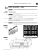
LGB 3ERIES 'AS &IRED "OILER "OILER -ANUAL 11 Replacement parts Base Insulation Table Base Size (Note 1) Base Insulation Size (Note 2) 4 4 5 5 A A B B C C D A and K E B and K F A and J G A and J Notes: 1. Base Arrangement Table, to determine base size for your boiler. 2. Contains one (1) each front and back.
s )NSTALLATION s 3TART 5P s -AINTENANCE s 0ARTS Item Description 1 Horizontal Draft Hood 2 Screw, Phillips #10 x1/2 3 Horizontal Collector Hood Size Weil-McLain Part Number Item 4 5 A B C D E F G 443-300-098 443-300-099 443-300-100 443-300-101 443-300-102 443-300-103 443-300-104 443-300-105 443-300-106 14 * 4 5 A B C D E F G 450-019-858 450-019-859 450-019-851 450-019-852 450-019-853 450-019-854 450-019-855 450-019-856 450-019-857 * * * 4 ! " $ % ' +; < 5 Washer, Plain 1/4- .
LGB 3ERIES 'AS &IRED "OILER "OILER -ANUAL 12 Boiler Model Number Dimensions Supply Tappings Return Tappings Dimensions in Inches Gas Connection Size Natural and Propane (Note 1) Draft Hood Outlet(s) 5" w.c. Natural No. Size No. Size No. Size A B C W No.
s )NSTALLATION s 3TART 5P s -AINTENANCE s 0ARTS 13 Equipment — standard and optional 2 % @ 2. 3. 4. 5. 6. 8.
LGB 3ERIES 'AS &IRED "OILER "OILER -ANUAL 14 Ratings - Steam (Note 3) Boiler Model Number (Note 1) Heating Medium Boiler Water Content Gallons Complete Approx. Assembled Packaged Shipping Block Boiler Weight Weight Weight Input MBH (Note 2) Gross Output MBH (Note 2) Net Rating Steam MBH (Note 2) Boiler H.P. Sq. Ft. Steam (to Waterline) WaterGallons lbs. Steam Models PLGB (Note 4) Chimney Breeching Size (I.D.) Inches (Note 5) LGB-4 Steam 400 312 234 9.
s )NSTALLATION s 3TART 5P s -AINTENANCE s 0ARTS 14 Ratings - Water (Note 3) Boiler Water Content Gallons Approx. Shipping Weight Assembled Block Weight Complete Packaged Boiler Weight Chimney Breeching Size (I.D.) Input MBH (Note 2) Gross Output MBH (Note 2) Net Rating Water MBH (Note 2) Boiler H.P. Gallons lbs. Water 400 322 280 9.7 36.5 1185 975 1600 10 LGB-5-W Water 520 419 364 12.6 45.6 1455 1200 1800 12 LGB-6-W Water 650 523 455 15.7 54.
LGB 3ERIES 'AS &IRED "OILER "OILER -ANUAL Notes 38 Part Number 550-141-186/0914
s )NSTALLATION s 3TART 5P s -AINTENANCE s 0ARTS Notes Part Number 550-141-186/0914
LGB 3ERIES 'AS &IRED "OILER "OILER -ANUAL Weil-McLain 500 Blaine Street Michigan City, IN 46360-2388 http://www.weil-mclain.