
Overview of Primary Product
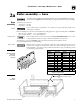

Part Number 550-141-186/0914
6
LGB
3ERIES'AS&IRED"OILER"OILER-ANUAL
!,
()
)
6ENTINGMUSTBEINSTALLEDACCORDINGTO0ART6ENTINGOF%QUIPMENTOF.ATIONAL&UEL'AS
#ODE!.3):nLATESTEDITIONANDAPPLICABLEBUILDINGCODES#ANADIANINSTALLATIONSMUST
COMPLYWITH#!.#3!"OR")NSTALLATION#ODE
Breeching must not be connected to any portion of mechanical draft system that can operate
under positive pressure.
At the time of removal of an existing boiler, the following steps shall be followed with each
appliance remaining connected to the common venting system placed in operation, while the
other appliances remaining connected to the common venting system are not in operation.
a. Seal any unused openings in the common venting system.
b. Visually inspect the venting system for proper size and horizontal pitch and determine
there is no blockage or restriction, leakage, corrosion and other deficiencies which could
cause an unsafe condition.
c. Insofar as is practical, close all building doors and windows and all doors between the space
in which the appliances remaining connected to the common venting system are located
and other spaces of the building. Turn on clothes dryers and any appliance not connected to
the common venting system. Turn on any exhaust fans, such as range hoods and bathroom
exhausts, so they will operate at maximum speed. Do not operate a summer exhaust fan.
Close fireplace dampers.
d. Place in operation the appliance being inspected. Follow the lighting instructions. Adjust
thermostat so appliance will operate continuously.
e. Test for spillage at the draft hood relief opening after 5 minutes of main burner operation.
Use the flame of a match or candle.
f. After it has been determined that each appliance remaining connected to the common vent-
ing system properly vents when tested as outlined above, return doors, windows, exhaust
fans, fireplace dampers, and any other gas-burning appliance to their previous conditions
of use.
g. Any improper operation of the common venting system should be corrected so the instal-
LATIONCONFORMSTOTHE.ATIONAL&UEL'AS#ODE!.3):nLATESTEDITION7HENRESIZING
any portion of the common venting system, the common venting system should be resized
to approach the minimum size as determined using the appropriate tables in Appendix G
INTHE.ATIONAL&UEL'AS#ODE!.3):nLATESTEDITION
#ANADIANINSTALLATIONSMUSTCOMPLYTO#!.#3!"OR")NSTALLATION#ODES
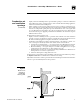
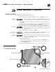
Flue gas spillage
1b
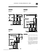
Pre-installation — venting
See Figures 3, 4 and 5ONPAGEFORTYPICALVENTINGCONlGURATIONS%NSURETHATYOURINSTALLATION
COMPLIESWITHTHEREQUIREMENTSGIVENINTHESEILLUSTRATIONSANDWITHALLLOCALCODESANDSTANDARDS
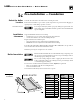
See the
Ratings table on page 36, for minimum breeching diameter. Use heavy gauge steel
breeching (Type B vent material or single wall metal pipe). Where horizontal breeching is
used, slope upward at least ¼” per foot toward chimney or vent and support with hangers to
prevent sagging.
Long horizontal breechings, excessive numbers of elbows or tees, or other
obstructions restricting flow of combustion gases can result in possibility
of flue gas spillage and carbon monoxide emissions, causing severe personal
injury or death.
Failure to follow all instructions listed below can cause flue spillage and
carbon monoxide emissions, resulting in severe personal injury, death or
substantial property damage.