
Overview of Primary Product

3
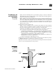
Base
assembly
4
Access shield
(sizes D,
E, F and G
shown)
Part Number 550-141-186/0914
s)NSTALLATIONs3TART5Ps-AINTENANCEs0ARTS
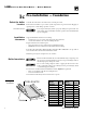
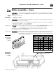
Check for proper orifice size:
s .ATURALGASnMM
s 0ROPANEGASnMM
Assembly order
Burner seating
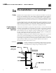
Before assembling base, relocate access shield from lower shipping holes to upper mounting holes. See Figure 7.
s "ASESIZES!"AND#ONEMOUNTINGHOLE
s "ASESIZES$%&AND'TWOMOUNTINGHOLES
Proper orifices must be used. Failure to do so will cause severe personal injury, death or sub-
stantial property damage.
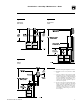
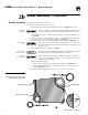
Assemble base(s) as shown in
Figure 8, in the order shown in the table below. Dual base shown.
Level and straighten burners to avoid misfiring.
Base assembly must be located in order shown in Base Arrangement Table, below, so flue
collector/draft hoods, jackets, and gas controls are installed in correct position.
Burners must be properly seated in their locating slots with openings facing up. Front of
burners must rest fully over main burner orifices. Gas orifices must inject down center of
burners. Failure to properly level and seat burners will result in severe personal injury, death
or substantial property damage.
2a
Boiler assembly — base
The boiler contains ceramic fiber and fiberglass materials. Use care when handling these materials
per instructions on page 28 of this manual. Failure to comply could result in severe personal injury.
Base Arrangement Table (Note 1)
Boiler
Model
Number
Base Size
Boiler
Model
Number
Base Size
LGB-4 4 --- LGB-14 CB
LGB-5 5 --- LGB-15 CC
LGB-6 A --- LGB-16 DC
LGB-7 B --- LGB-17 DD
LGB-8 C --- LGB-18 ED
LGB-9 D --- LGB-19 EE
LGB-10 E --- LGB-20 FE
LGB-11 F --- LGB-21 FF
LGB-12 G --- LGB-22 GF
LGB-13 BB LGB-23 GG
Note 1: From boiler left side (front view). Side panels
shipped in separate carton.
For dual
base only
where two base connect.
For dual
b
ase on
l
y
w
h
ere t
w