TM Wall Mount Gas-Fired Water Boilers 70/110/155 Boiler Manual s )NSTALLATION s -AINTENANCE s 3TARTUP s 0ARTS This manual must only be used by a qualified heating installer/service technician. Read all instructions, including this manual and all other information shipped with the boiler, before installing. Perform steps in the order given. Failure to comply could result in severe personal injury, death or substantial property damage.
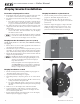
TM GAS-FIRED WATER BOILER — Boiler Manual The ECO Gas-fired water boilers 3TAINLESS STEEL lRETUBE HEAT EXCHANGER (EAT EXCHANGER ACCESS COVER BURNER MOUNTING PLATE 3. Blower The advanced blower design and air inlet silencer on ECO Wall Mount boilers result in very quiet operation. Air enters the boiler enclosure through the air intake adapter (16), flows through the enclosure, enters the air inlet silencer (5), then enters the blower.
TM GAS-FIRED WATER BOILER — Boiler Manual The ECO Gas-fired water boilers (cont.
TM GAS-FIRED WATER BOILER — Boiler Manual Contents The ECO Gas-fired water boilers. . . . . . . . . . . . . . . . 2 Please read before proceeding . . . . . . . . . . . . . . . . 5 Boiler location . . . . . . . . . . . . . . . . . . . . . . . . . 6 Wall-mounting the boiler. . . . . . . . . . . . . . . . . . . . 8 Display bracket installation . . . . . . . . . . . . . . . . . 10 Boiler hydrostatic test . . . . . . . . . . . . . . . . . . . . 11 Converting boiler to propane — ECO 70/110 . . . . . . . .
TM GAS-FIRED WATER BOILER — Boiler Manual Please read before proceeding (AZARD DElNITIONS The following defined terms are used throughout this manual to bring attention to the presence of hazards of various risk levels or to important information concerning the life of the product. Indicates presence of hazards that will cause severe personal injury, death or substantial property damage. Indicates presence of hazards that can cause severe personal injury, death or substantial property damage.
TM GAS-FIRED WATER BOILER — Boiler Manual Boiler location Installations must comply with: s s s s s s Local, state, provincial, and national codes, laws, regulations and ordinances. National Fuel Gas Code, ANSI Z223.1/NFPA 54. National Electrical Code. For Canada only: CAN/CSA B149.1, Natural Gas and Propane Installation Code, and any local codes. The ECO boiler gas manifold and controls met safe lighting and other performance criteria when boiler underwent tests specified in ANSI Z21.
TM GAS-FIRED WATER BOILER — Boiler Manual Boiler location (continued) Provide clearances for service access — RECOMMENDED Provide clearances from combustible materials — REQUIRED 1. See Figure 1 for recommended service clearances. 2. If you do not provide minimum service clearances shown, it might not be possible to service the boiler without removing it from the space. 3. Clearance D, Figure 1 allows for the installation of piping as shown in Figure 8, page 12 plus a close nipple and elbow. 1.
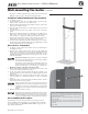
TM GAS-FIRED WATER BOILER — Boiler Manual Wall-mounting the boiler Remove boiler from crate &IGURE Boiler shipping container 4HE BOILER IS HEAVY. Use caution not to drop the boiler or cause bodily injury while lifting and handling. Verify that the boiler is securely attached to prevent possibility of boiler falling after installation. After the boiler is removed from the shipping carton, $/ ./4 allow the boiler to sit on its bottom.
TM GAS-FIRED WATER BOILER — Boiler Manual Wall-mounting the boiler (continued) ing stud or washer. Perform all procedures given in the Boiler Manual on previous pages before mounting the boiler. &IGURE Place boiler on wall-mount bracket Install the wall-mount bracket (by installer) 1. See Figure 4, page 8. 2. Locate the studs — must be on 16-inch centers. See previous page instructions if studs are not on 16-inch centers. 3.
TM GAS-FIRED WATER BOILER — Boiler Manual Display bracket installation Determine display unit location Display installation on junction box 1. Boiler display unit can be mounted on either the right side of the boiler jacket or on the wall in close proximity to the boiler 2. For displays mounted on the boiler jacket, use the provided display bracket. a. For boilers mounted using the optional floor stand kit, always mount the display to the display bracket on the boiler jacket.
TM GAS-FIRED WATER BOILER — Boiler Manual Boiler hydrostatic test $/ ./4 INSTALL A RELIEF VALVE WITH A PRESSURE HIGHER THAN 03)'. This is the maximum allowable relief valve setting for the ECO boiler. Failure to comply could prevent the relief valve from operating as needed, resulting in possibility of severe personal injury, death or substantial property damage. 5SE TWO WRENCHES WHEN TIGHTENING ANY PIPE CONNECTION TO THE BOILER.
TM GAS-FIRED WATER BOILER — Boiler Manual Boiler hydrostatic test (continued) &IGURE &IGURE Install pipe fittings for relief valve and pressure/temperature gauge — $/ Install piping components required for hydrostatic test (see legend below) .
TM GAS-FIRED WATER BOILER — Boiler Manual Converting boiler to propane — ECO 70/110 Prepare boiler for propane — ECO 70/110 only (if required) &IGURE Propane gas orifice bushing identification %#/ 70 on left (may be stamped 3.85) %#/ 110 on right (may be stamped 4.45) Propane operation !,, %#/ BOILERS MUST BE CONVERTED FOR PROPANE OPERATION.
TM GAS-FIRED WATER BOILER — Boiler Manual Converting boiler to propane — ECO 70/110 (cont.) &IGURE Installing the propane gas orifice bushing (some details omitted for clarity) 7. See Figure 12. Insert the propane gas orifice bushing (item 4) into the gas valve outlet as shown. 8. Press the bushing into the gas valve outlet until the bushing flange butts against the gas valve outlet. Inspect the O-rings on the propane gas orifice bushing an on the gas valve outlet (item 5, Figure 12).
TM GAS-FIRED WATER BOILER — Boiler Manual Converting boiler to propane — ECO 155 Prepare boiler for propane — &IGURE Propane gas orifice identification %#/ 155 ECO 155 only (if required) Propane operation !,, %#/ BOILERS MUST BE CONVERTED FOR PROPANE OPERATION. #ONVERTING AN EXISTING NATURAL GAS lRED BOILER FOR PROPANE — For a boiler already installed, you must turn off gas supply, turn off power and allow boiler to cool before proceeding.
TM GAS-FIRED WATER BOILER — Boiler Manual Converting boiler to propane — ECO 155 (cont.) &IGURE Installing the propane gas orifice bushing (some details omitted for clarity) ,%'%.
TM GAS-FIRED WATER BOILER — Boiler Manual Gas piping — sizing gas lines Boiler gas connection is ½” NPT. Size gas lines large enough to provide gas to all connected appliances. &IGURE Pipe capacity for 0.60 specific gravity natural gas; pipe length is in equivalent feet Natural Gas: 0IPE SIZING FOR NATURAL GAS 1. Size gas piping from meter outlet to entrance of boiler in accordance with Figure 16 and Figure 17. 2. Use total input of all connected appliances.
TM GAS-FIRED WATER BOILER — Boiler Manual Venting/air piping — general Do not install the ECO boiler into a common vent with any other appliance. This will cause flue gas spillage or appliance malfunction, resulting in possible severe personal injury, death or substantial property damage. Existing common vent systems may be too large for the appliances remaining connected after the existing boiler is removed.
TM GAS-FIRED WATER BOILER — Boiler Manual Venting & air — general (cont.) &IGURE ECO venting and air piping — DIRECT VENT ONLY — OPTIONS and PIPING LIMITS The table below lists the acceptable vent/air pipe terminations described in this manual. Follow all instructions provided to install the vent/air system. ./4 3(/7. below, but also approved, are the polypropylene piping and terminations listed in Figure 20, page 20.
TM GAS-FIRED WATER BOILER — Boiler Manual Venting & air — general (cont.
TM GAS-FIRED WATER BOILER — Boiler Manual Commonwealth of Massachusetts installations Commonwealth of Massachusetts — When the boiler is installed within the Commonwealth of Massachusetts, the boiler must be installed by a licensed plumber or gas fitter. Read and comply with the instructions below.
TM GAS-FIRED WATER BOILER — Boiler Manual Vent termination requirements &IGURE The vent termination must be located to meet all requirements below (also applies to vertical vent terminations). For Canadian installations, defer to the requirements of CSA B149.1 or B149.2 Installation Code.
TM GAS-FIRED WATER BOILER — Boiler Manual Boiler room air openings &IGURE Combustion and ventilation air openings for %#/ Direct Vent installations The ECO boiler CANNOT be in the same space with other appliances if clearances around the ECO are less than the recommended service clearances shown in Figure 1, page 7. Air openings ECO boiler WITH other appliances in room The required air opening sizes below are FREE AREA, after reduction for louver obstruction.
TM GAS-FIRED WATER BOILER — Boiler Manual DIRECT VENT — 3IDEWALL WITH SEPARATE PIPES !LLOWABLE VENT AIR PIPE MATERIALS LENGTHS &IGURE ).34!,,!4)/. 3%15%.#% — Separate pipes sidewall Use only the vent materials and kits listed in Figure 20, page 20. Provide pipe adapters if specified. 1. Locate the termination such that the total air piping and vent piping from the boiler to the termination will not exceed the maximum length given in Figure 19, page 19.
TM GAS-FIRED WATER BOILER — Boiler Manual DIRECT VENT — 3IDEWALL WITH SEPARATE PIPES (continued) See notices on previous page. &IGURE Multiple separate pipes sidewall terminations — maintain vertical spacing between vent and air fittings shown in Figure 23, page 24 All vent pipes and air inlets must terminate at the same height to avoid possibility of severe personal injury, death or substantial property damage. 2. Place wall penetrations to obtain minimum clearances shown in Figure 24 for U. S.
TM GAS-FIRED WATER BOILER — Boiler Manual DIRECT VENT — 3IDEWALL CONCENTRIC !LLOWABLE VENT AIR PIPE MATERIALS LENGTHS &IGURE ).34!,,!4)/. 3%15%.#% — Concentric horizontal 1. The concentric termination kit must be purchased separately. Use only the vent materials and kits listed in Figure 20, page 20. Provide pipe adapters if specified. 2.
TM GAS-FIRED WATER BOILER — Boiler Manual DIRECT VENT — 3IDEWALL CONCENTRIC (continued) See notices on previous page. &IGURE Termination location — concentric termination — multiple boilers — clearance from vent of one to air intake of the next )NSTALL TERMINATION CONCENTRIC PIPES 1. Assemble the vent termination as described for concentric terminations, on page 34. If necessary, you can shorten the lengths of the inner and outer pipes for a shorter finished assembly.
TM GAS-FIRED WATER BOILER — Boiler Manual DIRECT VENT — 3IDEWALL WITH 7 - VENT AIR PLATE !LLOWABLE VENT AIR PIPE MATERIALS LENGTHS &IGURE ).34!,,!4)/. — W-M sidewall vent/air plate Use only the vent materials and kits listed in Figure 20, page 20. Provide pipe adapters if specified. 1. Locate the termination such that the total air piping and vent piping from the boiler to the termination will not exceed the maximum length given in Figure 19, page 19.
TM GAS-FIRED WATER BOILER — Boiler Manual DIRECT VENT — 3IDEWALL WITH 7 - VENT AIR PLATE (continued) )NSTALL 7EIL -C,AIN VENT AIR CAP Vent/air pipes and W-M vent/air plate can be oriented in any of the configurations shown in Figure 29, page 28. !$!04%23 — Use adapters if using other than 3-inch PVC or CPVC. This is required for different materials (polypropylene or AL29-4C stainless steel) or if using 2-inch pipe.
TM GAS-FIRED WATER BOILER — Boiler Manual DIRECT VENT — 6ERTICAL WITH SEPARATE PIPES !LLOWABLE VENT AIR PIPE MATERIALS LENGTHS &IGURE Separate pipes vertical termination Use only the vent materials and kits listed in Figure 20, page 20. Provide pipe adapters if specified. 1. Locate the terminations such that the total air piping and vent piping from the boiler to the termination will not exceed the maximum length given in Figure 19, page 19.
TM GAS-FIRED WATER BOILER — Boiler Manual DIRECT VENT — 6ERTICAL WITH SEPARATE PIPES (continued) See notices on previous page. &IGURE Terminations for multiple boilers 0REPARE ROOF PENETRATIONS 1. Air pipe penetration: a. Cut a hole for the air pipe. Size the air pipe hole as close as desired to the air pipe outside diameter. 2. Vent pipe penetration: a. Cut a hole for the vent pipe. For either combustible or noncombustible construction, size the vent pipe hole at least 0.
TM GAS-FIRED WATER BOILER — Boiler Manual DIRECT VENT — 6ERTICAL CONCENTRIC !LLOWABLE VENT AIR PIPE MATERIALS LENGTHS &IGURE ).34!,,!4)/. 3%15%.#% — Concentric vertical 1. The concentric termination kit must be purchased separately. Use only the vent materials and kits listed in Figure 20, page 20. Provide pipe adapters if specified. 2.
TM GAS-FIRED WATER BOILER — Boiler Manual DIRECT VENT — 6ERTICAL CONCENTRIC (continued) See notices on previous page. &IGURE Vertical termination — 3” PVC concentric — single or multiple boilers 2. Place roof penetrations to obtain minimum clearance of 12 inches between the edges of adjacent vent pipes of other boilers for U. S. installations (see Figure 36). For Canadian installations, provide clearances required by CSA B149.1 or B149.2 Installation Code and a ULC S636 compliant vent kit. 3.
TM GAS-FIRED WATER BOILER — Boiler Manual Concentric termination, typical &IGURE 06# concentric termination assembly — DO NOT attach the rain cap until the termination has been inserted through the roof or wall and all supports have been installed. See LEGEND at right. See kit instructions for details of polypropylene kits. (sidewall or vertical) ,%'%.
TM GAS-FIRED WATER BOILER — Boiler Manual Vent and air piping and boiler connections Follow termination instructions &IGURE Boiler vent and air connections 1. Read and follow all instructions for the termination type used before proceeding with this page. Follow all instructions provided by vent pipe manufacturer. Use only materials from the manufacturers listed in Figure 20, page 20.
TM GAS-FIRED WATER BOILER — Boiler Manual Install water piping Use two wrenches when tightening water piping at boiler, using one of the wrenches to prevent the boiler interior piping from turning. Failure to support the boiler piping connections to prevent them from turning could cause damage to boiler components. General piping information !DDITIONAL CONTROLS IF REQUIRED The ECO control uses temperature sensors to provide both high limit protection and modulating temperature control.
TM GAS-FIRED WATER BOILER — Boiler Manual Direct Connect System Piping Diaphragm- or bladder-type expansion tank— Control fill pressure with the tank air charge pressure. Always check pressure and charge tank with tank removed from system to be sure reading is accurate. Boiler relief valve is set for 30 PSIG. Operating pressure of system, after temperature expansion above cold fill pressure, should not exceed 24 PSIG to avoid weeping of relief valve.
TM GAS-FIRED WATER BOILER — Boiler Manual Direct Connect System Piping Closed-type expansion tank: (continued) &IGURE Piping to closed -type expansion tank DO NOT use a closed-type tank if connecting to a water heater that is equipped with an automatic air vent. Figure 43 shows suggested piping when using a closed-type expansion tank, in which the air is directly in contact with tank water. Connect piping (½” or ¾”) from the air separator outlet to the tank fitting.
TM GAS-FIRED WATER BOILER — Boiler Manual Direct Connect System Piping (continued) System water piping methods (EAD LOSS THROUGH BOILER PIPING 1. See Figure 43 for the head loss through the boiler. Use boiler head loss values to size pump after determining other piping head loss values. 3YSTEM CIRCULATOR 1. Install a system circulator as shown in the piping diagram in the Direct Connect System Piping section on page 41. 2. This circulator must be supplied by the installer.
TM GAS-FIRED WATER BOILER — Boiler Manual Direct Connect System Piping (continued) Install relief valve 1. Install relief valve in 1 ” x 1 ” x ¾” (for 70/110) or 1 ¼” x 1 ¼” x ¾” (for 155) reducing tee piped from boiler supply (Figure 8, page 12). 2. Pipe the relief valve only as shown, in the location shown. 3. Connect discharge piping to safe disposal location, following guidelines in the 7!2.).' below.
TM GAS-FIRED WATER BOILER — Boiler Manual Direct Connect System Piping ZONE VALVE zoning – direct connection (Shown with optional DHW piping) See Figure 45. 1. This configuration is for zone valve systems that qualify to use direct connection piping based on the criteria on page 37 only. If system does not qualify, pipe using primary/secondary piping. See pages 43-49 for piping suggestions and guidelines. 2. Systems zoned with zone valves MUST use a by-pass pressure regulator (Taco 3196 shown). 3.
TM GAS-FIRED WATER BOILER — Boiler Manual Primary/Secondary System Piping Expansion Tank Location &IGURE 0IPING TO DIAPHRAGM OR BLADDER EXPANSION TANK Figures 46 and 47 show typical installation of the system expansion tank. It is highly recommended that you locate the air separator and expansion tank as shown in the suggested piping drawings on pages 47 - 49. Ensure that the expansion tank size will handle boiler and system water volume and temperature.
TM GAS-FIRED WATER BOILER — Boiler Manual Primary/Secondary System Piping Closed-type expansion tank: &IGURE Piping to closed-type expansion tank DO NOT use a closed-type tank if connecting to a water heater that is equipped with an automatic air vent. Figure 47, page 43 shows suggested piping when using a closed-t y p e expansion tank, in which the air is directly in contact w ith tank water. Connect piping (½” or ¾”) from the air separator outlet to the tank fitting.
TM GAS-FIRED WATER BOILER — Boiler Manual Primary/Secondary System piping System water piping methods .EAR BOILER PIPING &IGURE Estimated head loss of boiler loop piping and recommended circulators. 12 1. Connect boiler to system only as shown in Figure 46 and Figure 47, page 44. The primary/secondary piping shown ensures the boiler loop will have sufficient flow. Verify that the boiler loop piping matches closely with the listed criteria in the NOTICE below.
TM GAS-FIRED WATER BOILER — Boiler Manual Primary/Secondary System piping (continued) 3YSTEM CIRCULATORS AND ZONE CIRCULATORS 1. Install a system circulator or zone circulators as shown in the piping diagrams in the Primary/Secondary System Piping section in this manual. These circulators must be supplied by the installer. 3YSTEM OR ZONE CIRCULATORS mOW RATES 1. Size circulators based on the flow rate required to achieve the temperature change you needed.
TM GAS-FIRED WATER BOILER — Boiler Manual Primary/Secondary System piping (continued) Install relief valve 1. Install relief valve in 1 ” x 1 ” x ¾” (for 70/110) or 1 ¼” x 1 ¼” x ¾” (for 155) reducing tee piped from boiler supply piping tee (Figure 8, page 12). 2. Pipe the relief valve only as shown, in the location shown. 3. Connect discharge piping to safe disposal location, following guidelines in the 7!2.).' below.
TM GAS-FIRED WATER BOILER — Boiler Manual Primary/Secondary System piping (continued) ZONE VALVE zoning – primary/secondary &IGURE Zone valve zoning — primary/secondary (Shown with optional DHW piping) connection — a system circulator is required See Figure 50. 1. This configuration is for zone valve systems using a boiler loop connected as a secondary circuit off of a primary system loop.
TM GAS-FIRED WATER BOILER — Boiler Manual Primary/Secondary System piping (continued) Circulator zoning – primary/secondary &IGURE Circulator zoning plus optional DHW piping (Shown with optional DHW piping) See Figure 51. 1. This configuration is for circulator-zoned systems using a boiler loop connected as a secondary circuit off of a primary system loop. Systems zoned with circulators must pipe the boiler loop as a secondary circuit as show. 2.
TM GAS-FIRED WATER BOILER — Boiler Manual Primary/Secondary System piping Circulator zoning – Multiple temperature zones with primary/ (continued) &IGURE Circulator zoning with high- and low-temperature heating zones secondary (Shown with optional DHW piping) See Figure 52. 1. This configuration is for circulator-zoned systems with high- and low-temperature heating zones using a boiler loop connected as a secondary circuit off of a primary system loop.
TM GAS-FIRED WATER BOILER — Boiler Manual Multiple boiler installations &IGURE Side-to-side mounting of multiple ECO boilers Placing multiple boilers 1. Locate multiple boilers with spacings shown in Figure 53. 2. Provide indicated clearances around boilers for access and servicing. If recommended dimensions are not possible, provide at least the minimum clearances given on page 7. Also follow local codes. 3. Provide a minimum 30-inch walkway in front of the boilers to ensure accessibility. 4.
TM GAS-FIRED WATER BOILER — Boiler Manual Multiple boiler installations (continued) Sequencing multiple ECO boilers 1. Use a multiple-boiler controller, such as the Weil-McLain BCP, BMC or BSC, to sequence boilers. Locate temperature sensors as required in the controller manual. -AXIMUM CONNECTED LOAD PER MANIFOLD INCH MANIFOLD -"( INCH MANIFOLD -"( INCH MANIFOLD -"( Easy-Fit® piping installation 1. Main header and Easy-Fit® Manifold pipe sizing. a.
TM GAS-FIRED WATER BOILER — Boiler Manual Multiple boiler installations (continued) &IGURE Piping schematic — typical piping for multiple ECO boilers, using Weil-McLain Easy-Fit manifolds ,EGEND FOR &IGURE 1 Flow/check valve 11 Check valve or backflow preventer, as required by applicable codes 2 Isolation valves (when used) 12 Cold water supply 3 Cap 13 Supply water temperature control (when used) 4 Easy-Fit® Manifold (supply) — layout and size per page 51 5 Easy-Fit® Manifold (return) — layo
TM GAS-FIRED WATER BOILER — Boiler Manual Multiple boiler installations (continued) When using a multiple-boiler control with lead boiler rotation, it is recommended that the boiler connected to the DHW tank is always set as the last boiler to operate in the sequence so that space heat can be maintained during times of DHW demand. DHW tank piping with multiple ECO boilers DHW direct connection—single tank 1.
TM GAS-FIRED WATER BOILER — Boiler Manual Install condensate line Prepare condensate trap assembly 1. Remove the condensate trap kit from the accessories bag. 2. See Figure 59. The left image shows the complete condensate trap kit. 3. Remove the flexible drain tube nut, item 2. 4. Push the flexible tube gasket ring (item 3) onto the end of the flexible tube (item 1) as shown in Figure 59. The tube should extend through the gasket about ¼ inch. 5. Insert the flexible tube and gasket into the drain fitting.
TM GAS-FIRED WATER BOILER — Boiler Manual Gas piping ECO boilers are shipped ready to fire natural gas ONLY. You must install the propane orifice bushing if the boiler will be connected to propane. See page 13. Failure to comply could result in severe personal injury, death or substantial property damage. Connecting gas supply piping 5SE TWO WRENCHES when tightening gas piping at boiler, using one wrench to prevent the boiler gas line connection from turning.
TM GAS-FIRED WATER BOILER — Boiler Manual Field wiring %,%#42)#!, 3(/#+ (!:!2$ — For your safety, turn off electrical power supply at service entrance panel before making any electrical connections to avoid possible electric shock hazard. Failure to do so can cause severe personal injury or death. ECO boiler wiring The installation must comply with: National Electrical Code and any other national, state, provincial or local codes or regulations. In Canada, CSA C22.
TM GAS-FIRED WATER BOILER — Boiler Manual Field wiring Low voltage: 1. Mount multi-hole cord grip (provided) to desired low voltage knockout and secure with a locknut. 2. Thermostat, aquastat, limit devices, and outdoor temperature sensor wire pairs should be routed through the cord grip. 1. If routed through the bottom left knockouts, wires should be connected directly into the corresponding terminal block. 2.
TM GAS-FIRED WATER BOILER Field wiring — Boiler Manual (continued) Line voltage wiring (120 VAC) Make the following line-voltage connections, some of which depend on your system and how the ECO control will be programmed. The callouts below refer to Figure 64. &IGURE ECO LINE VOLTAGE input and output connections (120 VAC) P1 6!# 0OWER INPUT 1. Provide and install a fused disconnect or service switch (15-ampere rated recommended) as required by applicable codes. 1.
TM GAS-FIRED WATER BOILER Field wiring — Boiler Manual (continued) Low voltage wiring (24 VAC) &IGURE ECO LOW VOLTAGE input and output connections Make the following low-voltage connections, some of which depend on your system and how the ECO control will be programmed. The callouts below refer to Figure 65. The ECO control provides inputs for one DHW zone (priority) and one heating zone.
TM GAS-FIRED WATER BOILER — Boiler Manual Wiring diagram — schematic &IGURE %#/ schematic wiring diagram (see Figure 67, page 61 for legend and notes) 60 Part number 550-142-122/0513
TM GAS-FIRED WATER BOILER — Boiler Manual Wiring diagram — ladder &IGURE %#/ ladder wiring diagram (see Figure 66, page 60 for schematic wiring diagram) Part number 550-142-122/0513 61
TM GAS-FIRED WATER BOILER — Boiler Manual EXPRESS SETUP — using default settings -!.$!4/29 #/.42/, 3%44).'3 — The following settings must be checked and adjusted if necessary: BOILER MODEL and HIGH ALTITUDE in BOILER SETTINGS menu. See instructions on the following pages for menu access and control settings. 9. If the system is piped using primary/secondary system piping, reference the following pages for piping and control suggestions: a. General guidelines—pages 43-46. b.
GAS-FIRED WATER BOILER TM — Boiler Manual ECO control operation 4EMPERATURE SETTINGS — You must ensure that the ECO control is set for the proper water temperatures for the system. Excessive water temperature can cause significant property damage in some applications. -ULTI TEMPERATURE SYSTEMS — If the heating system includes circuits that require lower temperature water (radiant slab circuits, for example) as well as higher temperature circuits (DHW, finned tube baseboard, etc.
TM GAS-FIRED WATER BOILER — Boiler Manual ECO control operation (continued) &IGURE ECO control display screens and typical navigation 64 Part number 550-142-122/0513
TM GAS-FIRED WATER BOILER — Boiler Manual ESSENTIAL settings 4(% #/.42/, 3%44).'3 ,)34%$ "%,/7 -534 "% -!$% "%&/2% 34!24).' 4(% "/),%2. Failure to comply could result in incorrect operation of the boiler, causing possible severe personal injury, death or substantial property damage. Step 1 Read about menu access and navigation on page 66. Step 2 Turn OFF power to the boiler. Step 3 Turn off gas supply to the boiler by closing the boiler’s manual gas valve.
TM GAS-FIRED WATER BOILER — Boiler Manual ECO control settings menus &IGURE ECO control menu access — accessing contractor menus "%&/2% 02/#%%$).' PERFORM ESSENTIAL CONTROL SETTINGS AS INSTRUCTED ON PAGE . 5. The CONTRACTOR MENU screen will show: a. "/),%2 3%44).'3 SEE PAGE Control menus — OVERVIEW B (%!4).' 3%44).'3 SEE 1. Access contractor menus by pressing and holding the UP and DOWN arrow keys at the same time for 7 seconds. C $(7 3%44).'3 SEE 2.
TM GAS-FIRED WATER BOILER — Boiler Manual BOILER SETTINGS menu &IGURE "/),%2 3%44).'3 menu (see Figure 73 for setting values and descriptions) 2. The HIGH LIMIT TEMPERATURE setting will automatically return to 200°F if power is turned off. The boiler will restart when power is restored. 3. Use this control setting only to test the control’s high limit function. WWSD BOILER MODEL Check the BOILER MODEL against the model listed on the boiler’s rating plate.
TM GAS-FIRED WATER BOILER — Boiler Manual HEATING SETTINGS menu &IGURE (%!4).' 3%44).'3 menu (see &IGURE Typical outdoor reset curves Figure 77, page 70 for setting values and descriptions) HEATING SETTINGS 1. The heating settings menu is for setting control operation during space heating. The settings apply to zones controlled by the HEAT Input/output. See Figure 77, page 70 for a listing of menu parameters. /$ 2%3%4 -!8 2.
TM GAS-FIRED WATER BOILER — Boiler Manual HEATING SETTINGS menu (continued) &IGURE 3YSTEM 3ETTINGS 2ECOMMENDED 3YSTEM TYPE 2ECOMMENDED TEMPERATURES SUPPLY MAX Temp OD RESET MIN Temp SUPPLY MIN Temp OD RESET MAX Temp Fan-coil 190 0 140 70 &INNED TUBE BASEBOARD * $EFAULT SETTINGS 180 0 130 70 Cast iron baseboard 180 0 120 70 Cast iron radiators 180 0 120 70 Radiant – slab on grade 120 0 80 70 Radiant – thin slab 140 0 80 70 Radiant – below floor (staple up) 160 0
TM GAS-FIRED WATER BOILER — Boiler Manual HEATING SETTINGS menu (continued) &IGURE (%!4).' 3%44).'3 menu (see Figure 71, page 66 for access information) Units ,OW Value (IGH Value $EFAULT SUPPLY MAX °F 60 190 180 Required supply temp. at system design max. load SUPPLY MIN °F 60 190 130 Minimum supply temp. for system -ENU )TEM #OMMENT OD RESET MAX °F 50 100 70 Outdoor temp. at which supply target reaches min. OD RESET MIN °F –20 50 0 Outdoor temp.
TM GAS-FIRED WATER BOILER — Boiler Manual DHW SETTINGS menu (continued) /. $)&& Setting MAX ON TIME to off will cause the control to never switch to space heating while DHW call for heat is present. This could present a freeze hazard for some installations if the DHW aquastat were to remain closed indefinitely. 1. The temperature must drop this many degrees below target temperature for the boiler to come on when a call for heat is present on DHW input. /&& $)&& 1.
TM GAS-FIRED WATER BOILER — Boiler Manual DIAGNOSTIC menu &IGURE $)!'./34)#3 menu navigation (see Figure 71, page 66 for access information) Menus .EXT SCREEN .EXT SCREEN .EXT SCREEN .
TM GAS-FIRED WATER BOILER — Boiler Manual DIAGNOSTICS menu (continued) &IGURE $)!'./34)#3 menu details (see Figure 80, page 72 for access information) -ENU )TEM Units ,OW Value (IGH Value $EFAULT #OMMENT 4/ 2%3%4 !,, ()34/29 To reset all history and counters to zero: Enter the DIAGNOSTICS menu. Then press and hold !.$ #/5.4%23 4/ :%2/ the left and right arrows located below the display. Hold for 3 seconds. This will cause ALL history and counters to be deleted.
TM GAS-FIRED WATER BOILER — Boiler Manual DIAGNOSTICS menu (continued) &IGURE $)!'./34)#3 menu details (continued) (see Figure 80, page 72 for access information) -ENU )TEM Units ,OW Value (IGH Value $EFAULT #OMMENT 4/ 2%3%4 !,, ()34/29 To reset all history and counters to zero: Enter the DIAGNOSTICS menu. Then press and hold !.$ #/5.4%23 4/ :%2/ the left and right arrows located below the display. Hold for 3 seconds. This will cause ALL history and counters to be deleted.
TM GAS-FIRED WATER BOILER — Boiler Manual Startup — fill the system #LEAN SYSTEM TO REMOVE SEDIMENT !NTIFREEZE 1. You must thoroughly flush the system (without boiler connected) to remove sediment. The high-efficiency heat exchanger can be damaged by buildup or corrosion due to sediment. 1. Use only antifreeze listed by Weil-McLain as suitable for use with ECO Gas Boilers. See Figure 109, page 107 for information. 2.
TM GAS-FIRED WATER BOILER — Boiler Manual Startup — fill the system (continued) Freeze protection (if used) Follow these guidelines to prevent possibility of severe personal injury, death or substantial property damage: 5SE ONLY THE PRODUCTS LISTED BY7EIL -C,AIN FOR USE WITH THIS BOILER 3EE PAGE FOR INFORMATION 4HOROUGHLY mUSH ANY SYSTEM THAT HAS USED GLYCOL before installing the new ECO boiler. 2EVIEW THE MATERIAL SAFETY DATA SHEETS -3$3 are available online.
TM GAS-FIRED WATER BOILER — Boiler Manual Startup — final checks Inspect/fill condensate system Check for gas leaks Before starting the boiler, and during initial operation, use a leak detector or smell near the floor and around the boiler for gas odorant or any unusual odor. Remove boiler jacket door and smell the interior of the boiler jacket. $O NOT PROCEED WITH STARTUP IF THERE IS ANY INDICATION OF A GAS LEAK 2EPAIR ANY LEAK AT ONCE. $/ .
TM GAS-FIRED WATER BOILER — Boiler Manual Startup — final checks (continued) Final checks before starting boiler ❏ ❏ Read the instructions to adjust and set up the ECO control. ❏ Verify that the boiler model is set correctly in the ECO con- 1. Check around the boiler and inside the boiler jacket for gas odor following the procedure of page 55 of this manual. If you discover evidence of any gas leak, shut down the boiler at once. Find the leak source with bubble test and repair immediately.
TM GAS-FIRED WATER BOILER — Boiler Manual Startup — final checks (continued) &IGURE Operating instructions (WARNING — Verify that the ECO control is set for the correct boiler model before proceeding.
TM GAS-FIRED WATER BOILER — Boiler Manual Startup — final checks (continued) Throttle screw adjustment If combustion at either high or low fire is outside the range given in Figure 87, page 81, follow the procedure given on page 80 or page 81 for adjusting the throttle screw on the venturi. If throttle screw adjustment does not correct the problem, then shut down the boiler and contact your local WeilMcLain representative.
TM GAS-FIRED WATER BOILER — Boiler Manual Startup — final checks (continued) Throttle screw adjustment &IGURE Acceptable combustion values — %#/ /.,9 measured values must be within the ranges given below $/ ./4 attempt to adjust the throttle screw unless by a quali- fied technician, and with the use of calibrated combustion test instruments. Adjust the throttle screw only as needed to meet the combustion values given in Figure 87. 1.
TM GAS-FIRED WATER BOILER — Boiler Manual Check-out/startup verification Adjust and test boiler controls 1. Follow instructions in this manual to set and verify operation of the boiler controls. 2. Follow low water cutoff manufacturers instructions (if used). control manufacturers? (Boiler should be operating and should go off when controls are tested. Verify controls cause automatic reset lockout or manual reset lockout as desired.
TM GAS-FIRED WATER BOILER — Boiler Manual Annual startup and general maintenance Follow the service and maintenance procedures given throughout this manual and in component literature shipped with the boiler. Failure to perform the service and maintenance could result in damage to the boiler or system. Failure to follow the directions in this manual and component literature could result in severe personal injury, death or substantial property damage.
TM GAS-FIRED WATER BOILER — Boiler Manual Annual startup HANDLING CERAMIC FIBER MATERIALS 2%-/6).' "52.%2 '!3+%4 OR #/6%2 0,!4% ).35,!4)/. The ECO cover plate refractory contain ceramic fiber material. Ceramic fibers can be converted to cristobalite in very high temperature applications. The International Agency for Research on Cancer (IARC) has concluded, “Crystalline silica inhaled in the form of quartz or cristobalite from occupational sources is carcinogenic to humans (Group 1).
TM GAS-FIRED WATER BOILER — Boiler Manual Annual startup (continued) Clean condensate trap The boiler should be inspected and started annually, at the beginning of the heating season, only by a qualified service technician. In addition, the maintenance and care of the boiler designated in Figure 89, page 83 and explained on the following pages must be performed to assure maximum boiler efficiency and reliability. Failure to service and maintain the boiler and system could result in equipment failure.
TM GAS-FIRED WATER BOILER — Boiler Manual Annual startup (continued) s 1. Verify all system components are correctly installed and operational. Do not use automatic air vents in systems with closedtype tanks. The air will escape from the system instead of returning to the tank. s Eventually, the tank will waterlog and no longer control pressurization. The boiler relief valve will weep frequently.
TM GAS-FIRED WATER BOILER — Boiler Manual Annual startup (continued) Check ignition wiring 1. Check ignition cable electrical resistance. A good cable will have resistance between 950 and 1050 ohms. Replace if not acceptable. 2. Inspect boiler ground wire from heat exchanger access cover to ground terminal screw. 3. Verify all wiring is in good condition and securely attached. 4. Check ground continuity of wiring using continuity meter. 5. Replace ground wires if results are not satisfactory.
TM GAS-FIRED WATER BOILER — Boiler Manual Annual startup (continued) Check blower speeds 1. For installations at altitudes above 5,500 feet, make sure the control is set up for high altitude in the boiler setup menu. The ECO control automatically adjusts low fire and ignition rates to compensate for high altitude conditions.
TM GAS-FIRED WATER BOILER — Boiler Manual Annual startup (continued) Check boiler relief valve 1. Inspect the relief valve and lift the lever to verify flow as in the following warnings, excerpted from a relief valve manufacturer’s warning label. Before operating any relief valve, ensure that it is piped with its discharge in a safe area to avoid severe scald potential. 2. Read page 40 or 46 before proceeding further. 3.
TM GAS-FIRED WATER BOILER — Boiler Manual Troubleshooting VERIFY PROPER OPERATION AFTER SERVICING BEFORE TROUBLESHOOTING — Before calling for troubleshooting assistance, fill in the “%#/ 'AS $ATA #OLLECTION 3HEET” (page 122). Record the boiler size and CP number (located on the right side exterior of the boiler jacket). 1. See Figure 93 for tools and kits recommended for troubleshooting ECO boilers. 2. Check for 120 VAC (minimum 102 VAC to maximum 132 VAC) to boiler. 3.
TM GAS-FIRED WATER BOILER — Boiler Manual Troubleshooting (continued) &IGURE Control fuses Check ECO control fuses ALWAYS check ECO control fuses before replacing ECO control or any major components (blower, etc.). If one of these fuses is blown, it can prevent ECO control or other components from operating. 1. Turn OFF power to boiler at external line switch. Then remove the jacket door. 2. Locate fuses using Figure 95. 3. Remove and inspect the two fuses (items 1 and 2, Figure 95). 4.
TM GAS-FIRED WATER BOILER — Boiler Manual Troubleshooting (continued) -AKE SURE TO DETERMINE THE CAUSES OF OUTAGES $O NOT LEAVE THE BOILER OPERATING WITHOUT A COMPLETE DIAGNOSIS ECO control fault indications 1. The ECO control provided diagnostic information for automatic reset conditions, manual reset conditions, and certain functional warnings. See Figure 71, page 66 for information menu navigation and Figure 80, page 72 for DIAGNOSTIC screen information. &IGURE 2.
TM GAS-FIRED WATER BOILER — Boiler Manual Troubleshooting (continued) &IGURE Troubleshooting suggestions for ECO boilers — %#/ CONTROL %RROR #ONDITION ,OG The ECO control is able to record information about the boiler’s condition at the time of the three previous faults or errors. This information is available to view in Contractor Menus under “DIAGNOSTICS” by selecting “ERRORS.
TM GAS-FIRED WATER BOILER — Boiler Manual Troubleshooting (continued) &IGURE Troubleshooting suggestions for %#/ boilers — &AULT DISPLAYS DIAGNOSTICS AND CORRECTIVE ACTIONS Display Nothing shown on display screen and boiler will not respond to call for heat Nothing is shown in display screen and no other boiler components are operating Nothing is shown on display screen, but boiler is operating TEMP RISE TOO QUICKLY Condition Control is not receiving 24V power Control is not receiving 120V powe
TM GAS-FIRED WATER BOILER — Boiler Manual Troubleshooting (continued) &IGURE Troubleshooting suggestions for %#/ boilers — &AULT DISPLAYS DIAGNOSTICS AND CORRECTIVE ACTIONS Display TEMPERATURE SENSOR Condition Occurs if a temperature sensor has electrically TIPSUFE 4)035 PS IBT become disconnected (OPEN). Diagnostics Will automatically reset if the condition clears. Corrective Action(s) Check all the temperature readings of the boiler on the DIAGNOSTICS 5&.
TM GAS-FIRED WATER BOILER — Boiler Manual Troubleshooting (continued) &IGURE Display HIGH TEMP LIMIT Troubleshooting suggestions for %#/ boilers — &AULT DISPLAYS DIAGNOSTICS AND CORRECTIVE ACTIONS Condition Boiler temperature sensor SFBDIFE )JHI 5FNQ -JNJU setting (no higher than ¡' Diagnostics Reset using manual reset screen on display. Corrective Action(s) 7FSJGZ UIBU IJHI MJNJU TFUUJOH JT BU MFBTU ¡' BCPWF UIF TVQQMZ UBSHFU UFNQFSBUVSF %)8 #PJMFS 4VQQMZ BOE )FBUJOH 4VQQMZ .
TM GAS-FIRED WATER BOILER — Boiler Manual Troubleshooting (continued) &IGURE Troubleshooting suggestions for %#/ boilers — &AULT DISPLAYS DIAGNOSTICS AND CORRECTIVE ACTIONS Display IGNITION FAULT Condition Boiler went through 5 ignition attempts and never detected flame. Diagnostics Automatically resets after 1 hour or can be reset by performing manual reset on boiler. Corrective Action(s) Check condensate trap for blockage allowing condensate to accumulate inside heat exchanger.
TM GAS-FIRED WATER BOILER — Boiler Manual Maintenance Oiled bearing circulators DO NOT SERVICE THE BOILER WITHOUT A ECO MAINTENANCE KIT AVAILABLE 1. Check circulators in the system. Oil any circulators requiring oil, following circulator manufacturer’s instructions. Overoiling will damage the circulator. The ECO maintenance kit includes components that may have to be replaced when accessing or disassembling parts of the boiler.
TM GAS-FIRED WATER BOILER — Boiler Manual Maintenance (continued) Cleaning the heat exchanger WATER SIDE, when required 1. Isolate the boiler from the heating system. 2. Obtain Sentinel X400 cleaner from Weil-McLain. Follow instructions supplied with the cleaner to clean the boiler heat exchanger. Use ONLY the cleaning product available from WeilMcLain, Sentinel X400. See the Repair Parts section at the end of this manual for ordering information.
TM GAS-FIRED WATER BOILER — Boiler Manual Cleaning heat exchanger flue side, 70/110 Cleaning the ECO 70 or 110 heat exchanger FLUE SIDE or accessing the burner, if required The boiler contains ceramic fiber materials. Use care when handling these materials per instructions on page 84 of this manual. Failure to comply could result in severe personal injury.
TM GAS-FIRED WATER BOILER — Boiler Manual Cleaning heat exchanger flue side, 70/110 (continued) &IGURE Accessing the burner or heat exchanger (see Legend on page 100) Part number 550-142-122/0513 101
TM GAS-FIRED WATER BOILER — Boiler Manual Cleaning heat exchanger flue side, 70/110 (continued) )NSPECT AND CLEAN THE BURNER 1. See Figure 105, page 101 part D. a. Slide the refractory (item 12) over the burner and off. Set the refractory aside where it will be kept clean and protected from damage. If the refractory is damaged, it must be discarded and replaced with a new one. b. Remove the three #20 Torx screws (item 14) securing the burner (item 10) to the cover plate. Set aside. c.
TM GAS-FIRED WATER BOILER — Boiler Manual Cleaning heat exchanger flue side, 155 Cleaning the ECO 155 heat exchanger FLUE SIDE or accessing the burner, when required The boiler contains ceramic fiber materials. Use care when handling these materials per instructions on page 84 of this manual. Failure to comply could result in severe personal injury. 4OOLS REQUIRED 1. 2. 3. 4. 5. Metric wrench or socket, 10 mm. Phillips head screwdriver, #2. Socket with 8” extension, 5/16”. Torque wrench. Putty knife.
TM GAS-FIRED WATER BOILER — Boiler Manual Cleaning heat exchanger flue side, 155 (continued) DO NOT gouge or crack the refractory. The refractory is made of ceramic fiber materials. Read the ceramic fiber WARNING on page 84 before handling or disposing of ceramic fiber materials. c. When replacing the refractory, apply a ring of silicone adhesive on the cover plate. Place the refractory onto the cover plate.
TM GAS-FIRED WATER BOILER — Boiler Manual Cleaning heat exchanger flue side, 155 (continued) &IGURE Accessing the burner or heat exchanger (see Legend on page 104) Do NOT attempt to remove the burner from the heat exchanger cover plate without first removing the heat exchanger cover plate from heat exchanger. Damage to refractory will result. This damage is difficult to detect without the removal of the cover plate.
TM GAS-FIRED WATER BOILER — Boiler Manual Replacement parts DO NOT SERVICE THE BOILER WITHOUT A ECO MAINTENANCE KIT &AILURE TO ADHERE TO THESE GUIDELINES CAN RESULT IN SEVERE PERSONAL INJURY DEATH OR SUBSTANTIAL PROPERTY DAMAGE AVAILABLE The ECO maintenance kit includes components OBTAIN PARTS ONLY THROUGH WEIL-McLAIN that may have to be replaced when accessing or disassembling parts of the boiler.
TM GAS-FIRED WATER BOILER — Boiler Manual Replacement parts (continued) &IGURE Item Miscellaneous parts and kits Description 0ART .UMBER Item Antifreeze, Sentinel X500 . . . . . . . . . . . 592-900-004 Corrosion inhibitor, Sentinel X100 . . . . . . . 592-900-002 Sentinel X100 Quick Test Kit. . . . . . . . . . 592-900-005 Cleaner, Sentinel X400 . . . . . . . . . . . .
TM GAS-FIRED WATER BOILER — Boiler Manual Replacement parts (continued) &IGURE Jacket parts — ECO 70/110/155 (see Figure 111, page 109 for illustration) Item Name Description / contents Part Number 100 Jacket door Jacket door and labels 383-800-216 110 Seals – jacket door to cabinet Seals for front face of cabinet 383-800-217 120 Wall-mount bracket (wall side) Bracket and hardware 383-800-218 130 Wall-mount hardware (boiler side) Boiler mounting studs (bolts, washers, and spacers,
TM GAS-FIRED WATER BOILER — Boiler Manual Replacement parts (continued) &IGURE Jacket assembly — ECO 70/110/155 (see Figure 110, page 108 for part numbers) 'O TO WWW WEIL MCLAIN COM TO LOCATE 7EIL -C,AIN DISTRIBUTORS Part number 550-142-122/0513 109
TM GAS-FIRED WATER BOILER — Boiler Manual Replacement parts (continued) &IGURE Heat exchanger parts ECO 70/110 (see Figure 113, page 111 for illustration) Item Name Part Number 100 Heat exchanger 383-800-234 105 Heat exchanger with condensate dish, assembled (includes items 100, 120, 130, and 140) 383-800-235 110 Heat exchanger, condensate dish, cover plate, burner, igniter, sight glass, refractory, water sensors, gaskets, silicone, and hardware (includes items 100, 120, 130, 140, 160, 18
TM GAS-FIRED WATER BOILER — Boiler Manual Replacement parts (continued) &IGURE Heat exchanger assembly ECO 70/110 (see Figure 112, page 110 for part numbers) 'O TO WWW WEIL MCLAIN COM TO LOCATE 7EIL -C,AIN DISTRIBUTORS Part number 550-142-122/0513 111
TM GAS-FIRED WATER BOILER — Boiler Manual Replacement parts (continued) &IGURE Item Heat exchanger parts ECO 155 (see Figure 115, page 113 for illustration) Name Part Number 100 Heat exchanger 383-800-231 105 Heat exchanger with condensate dish, assembled (includes items 100, 160, 170 and 180) 383-800-232 110 Heat exchanger, condensate dish, cover plate, burner, igniter, sight glass, refractory, water sensors, gaskets, silicone, and hardware (includes items 100, 130, 140, 160, 170,180, 190
TM GAS-FIRED WATER BOILER — Boiler Manual Replacement parts (continued) &IGURE Heat exchanger assembly ECO 155 (see Figure 114, page 112 for part numbers) Part number 550-142-122/0513 113
TM GAS-FIRED WATER BOILER — Boiler Manual Replacement parts (continued) &IGURE Combustion components for ECO 70/110 (see Figure 118, page 115 for illustration) Item Name Description / contents Part Number 100 Relief valve Z[ \]>' ^ 110 Pressure & temperature gauge ] 200 Air inlet silencer Silencer 383-700-155 210 Silencer o-ring O-ring 590-318-049 220 Blower Blower, clip and gasket 383-700-157 230 Blower retainer clip Clip 56
TM GAS-FIRED WATER BOILER — Boiler Manual Replacement parts (continued) &IGURE Combustion components for ECO 70/110 /155(see Figure 116, page 114 for part numbers) 70/110 155 'O TO WWW WEIL MCLAIN COM TO LOCATE 7EIL -C,AIN DISTRIBUTORS Part number 550-142-122/0513 115
TM GAS-FIRED WATER BOILER — Boiler Manual Replacement parts (continued) &IGURE Controls and electrical components — ECO 70/110/155 (see Figure 120, page 117 for illustration) Item Name Description / contents Part Number 100 Flue temperature sensor One sensor 511-724-292 110 Outdoor temperature sensor One sensor 510-312-218 120 Transformer 120V/24V 50 VA transformer 511-802-011 130 Display board assembly Includes circuit board and plastic housing 381-330-019 140 Control module as
TM GAS-FIRED WATER BOILER — Boiler Manual Replacement parts (continued) &IGURE Controls and electrical assemblies — ECO 70/110/155 (see Figure 119, page 116 for part numbers) 'O TO WWW WEIL MCLAIN COM TO LOCATE 7EIL -C,AIN DISTRIBUTORS Part number 550-142-122/0513 117
TM GAS-FIRED WATER BOILER — Boiler Manual Dimensions &IGURE Dimensional data — ECO 70/110/155 (all dimensions in inches) 4/0 &2/.
TM GAS-FIRED WATER BOILER — Boiler Manual Ratings — ECO boilers &IGURE Ratings and engineering data — ECO 70/110/155 DOE Boiler Model ECO CSA Output / DOE Heating capacity CSA Input Net AHRI DOE water Seasonal rating Efficiency Boiler Water Content Vent/ Comb. Air Connection Diameter % Input derate vs vent length (Values shown are at MAX vent/air pipe length — See Note 6) $IRECT 6ENT 6ENTING /.
TM GAS-FIRED WATER BOILER — Boiler Manual Ratings — Multiple ECO boilers &IGURE Ratings and engineering data — multiple ECO boilers Boilers in SYSTEM Model %#/ 70 110 155 2 2 2 3 3 3 4 4 4 5 5 5 6 6 6 7 7 7 8 8 8 Boiler Model %#/ Total )NPUT /UTPUT (EATING CAPACITY Input, MBH Output, MBH - 140 220 310 210 330 465 280 440 620 Boiler ( 0 Net water RATINGS -ANIFOLDED COMBUSTION AIR DUCT SIZE - MBH Square inches Note 1 - Note 2 Figure 54, page 50 130 202 286 195 303 429 260 404
TM GAS-FIRED WATER BOILER — Boiler Manual Installation and Service Certificate "OILER 3TART 5P $ATA Boiler Model / Series ECO ________ / Series ____ CP Number ____________ Date installed ________________ CO2 @: High fire ______% Low fire ______% Btu Input ___________________ CO @: High fire ____ ppm Low fire ____ ppm FUEL: Natural ____ LP ____ Flame signal on control display at high fire __________________ Was orifice changed? _________ Flame signal on control display at low fire __________________ Was
TM GAS-FIRED WATER BOILER — Boiler Manual ECO Gas Boiler Data Collection Sheet #USTOMER )NFO Contact: Contractor: Job name: City, state: Distributor: 3YSTEM #OMPONENTS Near boiler pipe size: DHW tank (yes/no): DHW direct/system: DHW model: DHW pipe size: DHW circulator model: Is there air in system?: $IAGNOSTIC %RRORS Control fault: Ignition retries: Manual reset CNT: Auto reset CNT: 3OFTWARE 6ERSIONS Display: Main micro: Second micro: ,OCKOUT (ISTORY Fault Name: Fault Type: Fault Time: Fault Date
TM GAS-FIRED WATER BOILER — Boiler Manual NOTES Part number 550-142-122/0513 123
TM 124 GAS-FIRED WATER BOILER — Boiler Manual Part number 550-142-122/0513