SGO-W SERIES 3 OIL-FIRED NATURAL DRAFT WATER BOILER This Manual Includes: Installation Start-Up Boiler Parts Installer: • Make sure this is the correct manual for the boiler. Verify boiler model on rating label. • Leave all documentation received with boiler and burner with unit for future reference. User: Boiler and burner must be installed and serviced by qualified service technician. Part No.
Read This Page First Hazard Definitions The following terms are used to bring attention to the presence of hazards of various risk levels or to important information concerning product life. Indicates presence of hazards that will cause severe personal injury, death or substantial property damage if ignored. Indicates presence of hazards that can cause severe personal injury, death or substantial property damage if ignored.
Table of Contents Read all instructions before installing. Failure to follow all instructions in proper order can cause severe personal injury, death or substantial property damage. Read This Page First . . . . . . . . . . . . . . . . . . . . . . . . . . Table of Contents . . . . . . . . . . . . . . . . . . . . . . . . . . . . Before Installing Boiler . . . . . . . . . . . . . . . . . . . . . . . Install Non-Packaged Boiler . . . . . . . . . . . . . . . . . . . . Connect Breeching . . . . . . . . . . . . .
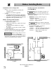
Before Installing Boiler Installations must comply with: • U.S. — State and local plumbing, heating and electrical codes. — National codes where applicable. Canada — Canadian Standards Association, CSA B139, Installation Code for Oil-Burning Equipment. — CSA C22.1 Canadian Electrical Code Part One. — Applicable local or provincial codes.
Before Installing Boiler Provide air for combustion and ventilation: • Adequate combustion and ventilation air: • Assures proper combustion. • Reduces risk of severe personal injury or death from possible flue gas leakage and carbon monoxide emissions. Do not install exhaust fan in boiler room. • Older buildings with single-pane windows, minimal weather-stripping and no vapor barrier often provide enough natural infiltration and ventilation without dedicated openings.
Install Non-Packaged Boiler Fiberglass wool and ceramic fiber materials: • POSSIBLE CANCER HAZARD BY INHALATION • CAN CAUSE RESPIRATORY, SKIN AND EYE IRRITATION This product contains fiberglass wool and ceramic fiber materials. Airborne fibers from these materials have been listed by the State of California as a possible cause of cancer through inhalation. Apply special care when handling ceramic fiber (chamber lining, base insulation) materials.
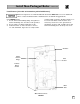
Install Non-Packaged Boiler 3. A-SGO-7, 8 & 9W — install flue collector hood (see FIGURE 2): Obtain gas-tight seal to prevent possible flue gas leakage and carbon monoxide emissions, leading to severe personal injury or death. a. Thread tinnerman clip on screw so that clip fits snugly in notch of hold-down lug. Screw must not turn. b. Remove paper on sealing rope. Starting at back section near flue collar, position sealing rope around top of block with adhesive side to sections. Do not stretch rope.
Install Non-Packaged Boiler Install jacket (sizes 7 through 9 only): Before installing jacket, remove burner mounting door. See jacket instructions for details. Install boiler controls: See Control Tapping Table and FIGURES 3 and 4 to install controls. 1. Install tankless heater control if tankless heater is used. If not furnished, use operating control with maximum 10°F differential. 2. Install limit control. If not furnished, use high limit with maximum 220°F setting. 3.
Install Non-Packaged Boiler CONTINUED Install burner (also refer to instructions packed with burner): Burners designed for use with Weil-McLain 68 boilers must not be used on GOLD Oil boilers. Contact individual burner manufacturers for GOLD Oil applications. For A-SGO-W boiler: 1. Secure universal mounting flange and gasket to burner mounting door. Use three bolts provided. 2. Secure burner on flange with three bolts. 3. Position burner so end of air tube is level to 1½° tilt downward.
Connect Breeching General chimney requirements: • Insufficient draft can cause flue gas leakage and carbon monoxide emissions, which will lead to severe personal injury or death. • • Use vent material approved by local codes for oil-fired burners. In their absence, refer to: — NFPA 31, Installation of Oil-Burning Equipment. — NFPA 211, Standard for Chimneys, Fireplaces, Vents and Solid Fuel Burning Appliances. — In Canada, refer to CSA B139, Installation Code for Oil-Burning Equipment.
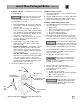
Connect Breeching CONTINUED Typical Location for Barometric Control (Also see Control Manufacturer’s Instructions) Flue Pipe Bracket (One on Each Side of Pipe) Back Outlet Breeching Connection FIGURE 5 Typical Location for Barometric Control (Also see Control Manufacturer’s Instructions) Flue Pipe Bracket (One on Each Side of Pipe) Top Outlet Breeching Connection FIGURE 6 11
Connect Water Piping General piping information: • • • • If installation is to comply with ASME or Canadian requirements, an additional high temperature limit is needed. Install control in supply piping between boiler and isolation valve. Set control to a minimum of 20°F above set point of combination control. Maximum allowable set point is 220°F. Wire control as shown on wiring diagram. Use a low water cutoff device when: — Boiler is installed above radiation level.
Connect Water Piping Isolation Valve Cold Water Fill Relief Valve CONTINUED Automatic Air Vent Alternate Location To Diaphragm Expansion Tank and Fittings Isolation Valve Pump From System Isolation Valve To Diaphragm Expansion Tank and Fittings Piping with DIAPHRAGM Expansion Tank FIGURE 7 Cold Water Fill Relief Valve Closed Type Expansion Tank To System Isolation Valve Pump From System Isolation Valve Piping with CLOSED Expansion Tank FIGURE 8 13
Connect Water Piping CONTINUED Piping MULTIPLE ZONES: 1. Follow instructions on page 12 and 13 to install piping near boiler. 2. See FIGURE 9 or 10 to complete installation 3. Zoning with circulators: a. Size each circulator to individual circuit requirements. b. Remove circulator (when furnished as standard equipment). c. Install balancing valves to adjust flow to distribute heat to all zones. d. Separate relay is required for each circulator. 4. Zoning with zone valves: a.
Connect Water Piping CONTINUED Recommended piping for systems requiring temperatures below 140°F: In most systems, this type of piping is not required. If system water temperature requirements are less than 140°F, such as radiant panels or converted gravity systems, use piping as shown in FIGURE 11 or 12. If system piping is plastic without an oxygen barrier, a heat exchanger must be used.
Connect Water Piping CONTINUED Use with refrigeration systems: • • Install boiler so that chilled medium is piped in parallel with heating boiler. Use appropriate valves to prevent chilled medium from entering boiler. Consult I=B=R Installation and Piping Guides. If boiler is connected to heating coils located in air handling units where they can be exposed to refrigerated air, use flow control valves or other automatic means to prevent gravity circulation during cooling cycle. Supply Exp.
Connect Tankless Heater Piping Studies have indicated that dangerous bacteria can form in potable water distribution system if certain minimum water temperatures are not maintained. Contact local health department for more information. TANKLESS HEATER RATINGS TABLE To pipe tankless heater: 1. Size piping no smaller than tankless heater inlet and outlet. 2. Following controls (furnished by others) must be installed: a. Automatic mixing valve. See FIGURE 14. (Read at bottom of p. 16) b.
Connect Wiring General wiring requirements: Junction box (furnished): • Electric shock hazard. Can cause severe personal injury or death if power source, including service switch on boiler, is not disconnected before installing or servicing. • • • Installations must follow these codes: — National Electrical Code, ANSI/NFPA 70, latest edition and any additional national, state or local codes. — In Canada, CSA C22.1 Canadian Electrical Code Part 1 and any local codes. Wiring must be N.E.C. Class 1.
Connect Wiring CONTINUED 19
Connect Oil Piping General oil piping requirements: • • • • Location and installation of oil tanks, oil piping and burners must follow: — NFPA 31, Standard for the Installation of Oil-Burning Equipment. — In Canada, CSA B139, Installation of Oil-Burning Equipment. — Local codes and regulations. — Information provided with burner and fuel pump. If any part of fuel oil tank is above level of burner, an anti-siphon device must be used to prevent flow of oil in case of oil line break.
Start-Up Follow information below to prevent severe personal injury, death or substantial property damage: • Do not use gasoline crankcase drainings or any oil containing gasoline. See burner manual for proper fuel oil. • Do not attempt to start burner when excess oil has accumulated, when unit is full of vapor or when combustion chamber is very hot. • Do not start burner unless collector hood, flue cap, jacket cap, breeching and burner mounting door are secured in place.
Check-Out Procedure Check off steps as completed: ❏ ❏ ❏ 1. Boiler and heat distribution units filled with water? ❏ 4. Air purged from oil piping? Piping checked for leaks? ❏ 5. Flue cap in place and tightened? Burner door closed, sealed and nut tight? Burner plugged in and service switch on? 2. Automatic air vent, if used, opened one full turn? 3.
Appendix Burner adjustments for “A” boilers: Final burner adjustments must be made using combustion test equipment to assure proper operation. Do not fire boiler without water or sections will overheat. 1. Refer to burner manual for start-up. 2. Allow boiler to heat to design condition. 3. Using combustion test equipment, adjust burner for: a. CO2 between 11% and 12% and 0 smoke. b. -0.01" to -0.02" W.C. draft in combustion chamber.
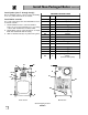
Parts List Repair parts must be purchased through Weil-McLain for the specific boiler as indicated in the list below. Results from using modified or other manufactured parts will not be covered by warranty and may damage boiler or impair operation. Fig. No.
Parts Drawing S D F E R G B A J L J J M J G K G C P N Q H 25
Dimensions 20 1/4 [514.4] 7 /4 [196.9] 3 DIMENSIONS - in. BOILER MODEL NUMBER B L SGO-3W 13 1/2 16 7 /8 SGO-4W 16 5/8 20 SGO-5W 19 7/8 231/8 SGO-6W 23 26 1/4 SGO-7W 26 1/8 29 3/8 SGO-8W 29 /4 32 /2 SGO-9W 32 3/8 35 5 /8 Water Supply Piping 1 101/4 [260.4] 355/8 [904.88] 43/8 DIA [111.1] Burner Opening 301/16 [763.6] Return 9 1/2 [241.3] 1 27/16 [61.9] 27/16 [61.9] 1 1/8 [28.6] SGO-W Front DIMENSIONS - mm. 7 3/16 [182.6] BOILER MODEL NUMBER B L SGO-3W 342.9 428.
Dimensions CONTINUED Intermediate 7 DIA [177.8] 61/4 [158.8] 7 DIA R [177.8] 299/16 [750.
Ratings SGO-W GOLD OIL WATER BOILER RATINGS (1) I=B=R BURNER CAPACITY GPH (3) * * -SGO-3W ROUND DRAFT FLUE BOILER LOSS OUTLET WATER THRU ROUND HEIGHT SIZE CONTENT BOILER IN FT IN (7) GAL IN W.C. (8) DOE HEATING CAPACITY (4) MBH (2) NET I=B=R RATINGS (5) DOE SEASONAL EFFICIENCY % AFUE 0.95 115 100 85.3 8x8 6 15 7 14.6 .020 * *-SGO-4W 1.20 145 126 85.0 8x8 6 15 7 16.3 .010 * *-SGO-5W 1.45 175 152 85.0 8x8 7 15 7 18.8 .015 * *-SGO-6W 1.75 212 184 85.