
Operating instructions


Part number 550-141-887/0800
13
AHE Series 4 Direct Vent Wall-Mounted Boilers — Boiler Manual
2c Venting — back venting installation con’t
Prepare mounting panel
continued
Inside
8. Insert inside cover plate assembly into opening.
Inside wall sleeve fits into outside wall sleeve. “Up”
stamp must be up.
9. Insert tube into top opening, until it stops. Mark
length ½" longer than plate. Cut tube.
10. Repeat step 9 for lower tube.
11. Remove inside cover plate assembly.
12. Apply generous bead of silicone sealant around
insertion end of tubes, 1" from end of tube.
Silicone sealant must be used where
indicated. Vent/air intake system
must be sealed gas-tight to prevent
possibility of flue gas spillage and
carbon monoxide emissions,
resulting in severe personal injury,
death or substantial property
damage.
13. Insert longer tube in top opening of outside plate,
shorter tube in bottom opening. See Figure 9.
14. Fit inside wall plate into opening. See step 8, above.
Tubes should protrude from plate. Do not fasten
plate to wall. See Figure 9.
15. Apply continuous bead of silicone sealant around
junctions of tubes and inside cover plate. Smooth
sealant to provide thorough seal. See Figure 10.
16. Using mounting panel as template, align (2)
plenum box openings over intake and exhaust
tubes. Level and mark location of (2) lag screw
holes. Drill (2)
3
/
16
" holes.
17. Hang mounting panel. Use (2)
5
/
16
" x 2¼" lag screws
provided. Use toggle bolts on plywood.
Reassembly
When vent/air intake system is disconnected for any
reason, reassemble and reseal per this manual section.
Silicone sealant must be used where
indicated. Vent/air intake system
must be sealed gas-tight to prevent
possibility of flue gas spillage and
carbon monoxide emissions,
resulting in severe personal injury,
death or substantial property
damage.
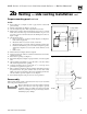
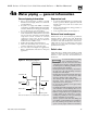
Figure 9 Back venting installation
Fasteners
88710
Silicone
sealant
Sealant
Sealant
½"
Sealant
Silicone
sealant
Screw
Screw
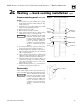
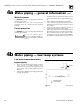
Figure 10 Inside cover plate
Silicone sealant
88711