
Operating instructions


Part number 550-141-887/0800
19
AHE Series 4 Direct Vent Wall-Mounted Boilers — Boiler Manual
6 Field wiring
For your safety, turn off electrical
power supply at service entrance
panel before making any electrical
connections to avoid possible shock
hazard. Failure to do so can cause
severe personal injury or death.
Wiring must be N.E.C. Class 1.
Boiler must be electrically grounded
as required by National Electrical
Code ANSI/NFPA 70–latest edition.
If original wiring as supplied with
boiler must be replaced, use only
type 105 °C wire or equivalent.
If original rollout thermal fuse
element wire as supplied with boiler
must be replaced, type 200 °C wire
or equivalent must be used.
Electrical installation must
comply with:
1. National Electrical Code and any other national,
state, provincial or local codes or regulations.
2. In Canada, CSA C22.1 Canadian Electrical Code
Part 1, and any local codes.
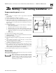
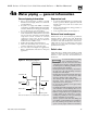
Wiring connections
Boiler is shipped with controls completely wired.
Electrical supply to boiler should be a separate branch
circuit with a fused disconnect (15 amp.).
Wire electric supply to supply leads in junction box.
Refer to wiring diagram inside jacket door or on page
23.
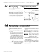
For addition of zone valves to system, a separate
transformer is required to power zone valves. Refer to
manufacturer’s recommendations for sizing
requirements and wiring recommendations. Zoning
with circulators requires a relay for each circuit.
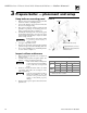
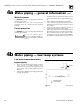
Thermostat
1. Connect thermostat to control wire harness inside
boiler, as shown on wiring diagram inside jacket
door, or manual page 23.
2. Install on inside wall away from influences of drafts,
hot or cold water pipes, lighting fixtures, television,
sunrays, or fireplaces.
3. If thermostat has a heat anticipator, set heat
anticipator in thermostat to match power
requirements of equipment connected to it. Refer
to wiring diagram on jacket door. For multiple
zoning, set the heat anticipator to match the current
draw of the zone valve.
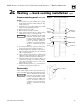
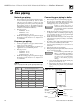
7 Jacket installation
Assemble jacket as shown in Figure 31, page 43,
using the appropriate Jacket Assembly Carton for
your boiler model.
Mounting
1. Bend corner tabs on mounting panel toward boiler.
2. Slide jacket assembly (without front panel) over
mounted boiler.
3. Upper back lip hooks over top of mounting panel.
4. Jacket swings toward mounting panel and snaps
into place.
5. Slide front panel upper lip under grill. Place against
side panels. Slide down until lower lip hooks behind
bottom panel edge.