
Operating instructions


Part number 550-141-887/0800
9
AHE Series 4 Direct Vent Wall-Mounted Boilers — Boiler Manual
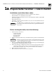
2b Venting — side venting installation
Prepare mounting panel
Inside
Refer to Figure 3, below, and Figure 32, page 44. Choose
right or left instructions based on venting direction.
1. Remove right (or left) knockouts.
2. Remove right (or left) intake and exhaust cover
plates and discard.
3. Cut round opening in top exhaust gasket using new
cover plate as template. Attach gasket and cover
plate.
4. Seal back intake and exhaust holes by placing a
generous amount of silicone sealant on the back
side of the mounting panel around each opening.
See Figure 2.
5. Mount blank cover plate (provided) over openings
using (4) #10 x ½" Phillips screws (provided).
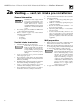
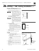
Figure 1 Side venting access to outside wall
88701
47½"
maximum
(including wall
thickness)
14" minimum
clearance to slide
panel over tubes
(right venting only)
6" min.
clearance to slide
panel over tubes
(left venting only)
38¼"
maximum
(including wall
thickness)
Exterior room wall
Exterior
room wall
Note: Tubes can be enclosed minimum of 1" clearance
from tubes to combustible material.
Select location
Review all connection, clearance and vent/air intake
considerations before selecting location. See Figure 1
for side venting clearance access to outside wall.
Continued next page...
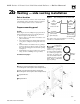
Figure 3 Side venting mounting panel
1
1
2
2
3
3
4
4
88702
1
Exhaust cover plate and gasket (Factory-assembled on
mounting panel. Remove right or left for venting direction.)
2
Intake cover plate and gasket (Factory-assembled on
mounting panel. Remove right or left for venting direction.)
3
Supplied with boiler
4
Supplied with kit
Figure 2 Sealant application
Sealant must
be placed on
stainless steel portion of
exhaust (top) opening to
provide gas-tight seal. Failure
to seal holes gas-tight can
cause flue gas spillage and
carbon monoxide emissions,
resulting in severe personal
injury, death or substantial
property damage.
Silicone
sealant
88703