80 Water & steam boilers for use with Gas, Light Oil, & Gas/Light Oil – Fired Burners Boiler Manual INSTALLER USER This manual must only be used by a qualified heating installer/service technician. Read all instructions before installing. Follow all instructions in proper order. Failure to comply could result in severe personal injury, death or substantial property damage. • Consider piping and installation when determining boiler location.
Weil-McLain 80 Boiler For Gas, Light Oil, Gas/Light Oil Fired Burners Contents Page 1. Before installing boiler .................................................................................. 3 2. Set boiler in place........................................................................................... 5 3. Assemble block .............................................................................................. 6 4. Perform hydrostatic pressure test .....................................
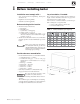
• Installation 1 • Start-Up • Maintenance • Parts Before installing boiler Installation must comply with — Lay a foundation, if needed: • Floor construction and condition must be suitable for weight of boiler when filled with water. See page 34 for approximate boiler operating weight. A level concrete or brick foundation (constructed per Table 1 and Figure 1) is required when: • • State, provincial and local plumbing, heating and electrical codes. Regulations of servicing utilities.
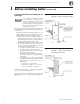
Weil-McLain 80 Boiler For Gas, Light Oil, Gas/Light Oil Fired Burners 1 Before installing boiler Provide combustion and ventilation air openings: Do not install an exhaust fan in boiler room. Adequate combustion and ventilation air must be provided to assure proper combustion and prevent possibility of flue gas leakage and carbon monoxide emissions, causing severe personal injury or death. Opening sizes must comply with state, provincial or local codes.
• Installation 2 • Start-Up • Maintenance • Parts Set boiler in place For packaged boiler: 1. Remove top jacket panels. Set aside until after boiler is piped. 2. 3. 4. 5. 6. The boiler contains ceramic fiber and fiberglass materials. Use care when handling these materials per instructions on page 38 of this manual. Failure to comply could result in severe personal injury. Remove lag screws (2 in front, 2 in rear) from shipping rails. Remove boiler from skid.
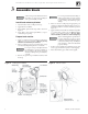
Weil-McLain 80 Boiler For Gas, Light Oil, Gas/Light Oil Fired Burners 3 Assemble block Sections are top heavy. Unbolted sections may fall if not supported, resulting in severe personal injury or death. Install back refractory blanket 1. Lay back section on floor with ports face up. 2. Apply adhesive to blanket. 3. Press blanket against back target wall as shown in Figure 4. 4. Using knife, cut hole through blanket to expose observation port opening. Prepare back section 1.
• Installation 3 • Start-Up • Maintenance Assemble block • Parts (continued) Install intermediate sections Figure 6 Sealing ring installation and port alignment Sections are top heavy. Unbolted sections may fall if not supported, resulting in severe personal injury or death. 1. Remove and discard 3/8" diameter shipping tie rods. 2. Remove grit from port machined surfaces with clean rag. Do not use petroleum-based cleaning or sealing compounds in boiler system.
Weil-McLain 80 Boiler For Gas, Light Oil, Gas/Light Oil Fired Burners 4 Perform hydrostatic pressure test Prepare boiler and test: 1. See pages 28 and 29 for tapping locations. Install: a. Boiler drain (not furnished). b. Water pressure gauge — for test only. Be sure gauge can handle test pressure — see step 3. c. Air vent in upper tapping (K). 2. Plug remaining tappings. Do not pressure test with any control installed. Damage to control can occur due to overpressure. 3. Fill boiler. Vent all air.
• Installation 5 • Start-Up • Maintenance • Parts Complete block assembly Install burner mounting plate on front section 1. Install four ½" x 4¾" studs to secure burner mounting plate to section: a. Thread and lock together two nuts on rounded end of stud. Thread flat end of stud into one of four holes located around opening. b. Remove nuts. c. Repeat steps a and b for remaining studs. 2. Install burner mounting plate: a.
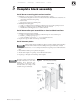
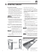
Weil-McLain 80 Boiler For Gas, Light Oil, Gas/Light Oil Fired Burners 6 Install flue collector Flue collector assembly 1. Figure 10, page 11, shows flue collector components and locations. Figure 11, page 13, shows collector hoods for all models. Follow all instructions in this manual to ensure correct installation of the flue collector. 2. Model 80 boilers are available with either rear flue or top flue. Verify that you have the correct components for your application.
• Installation 6 Figure 10 • Start-Up • Maintenance Install flue collector • Parts (continued) Flue collector components, typical (Model 880 collector configurations shown) Part No.
Weil-McLain 80 Boiler For Gas, Light Oil, Gas/Light Oil Fired Burners 6 Install flue collector Before installing flue collector 1. See Figure 10, page 11, for general assembly of flue collector components. 2. See Figure 11, page 13 for the placement of flue collector hoods on each model. 3. Prepare mounting holes in boiler rear section. a. The boiler rear section has tapped holes for mounting rear flue collector component. b. Remove any grit from threads inside tapped holes with clean rag.
• Installation 6 Figure 11 • Start-Up • Maintenance Install flue collector • Parts (continued) Flue collector components by model (see Figure 10, page 11 for flue collector components not shown below) Part No.
Weil-McLain 80 Boiler For Gas, Light Oil, Gas/Light Oil Fired Burners 7 Connect water boiler piping General water piping information: • • • Table 6 Recommended minimum pipe sizes for known flow rates. Table 7 ASME drain valve size System water supply and return piping should be installed and piping connections attached to boiler before erecting jacket or installing controls. Do not pipe in through supply and out through return. This creates reverse water flow through boiler that must not be used.
• Installation 7 • Start-Up • Maintenance • Parts Connect water boiler piping 3. Piping for multiple boilers (see Figure 13): A Size secondary boiler pump GPM based on following formulas: Gross output Temperature rise x 500 (continued) Figure 13 Multiple water boiler piping = GPM Temperature rise, °F = 230°F – Return water temperature Gross output is in Btuh. Calculate only secondary piping circuit resistance.
Weil-McLain 80 Boiler For Gas, Light Oil, Gas/Light Oil Fired Burners 8 Connect steam boiler piping General steam piping information: • Hartford loop piping arrangement and wet return are required for steam boilers. Use the Hartford loop for both pumped-return and gravity-return systems. • Maintain 24-inch minimum from waterline to bottom of header (56¼" from bottom of section). • When using condensate receiver, feed pump must be energized by boiler-mounted pump controller.
• Installation 8 • Start-Up • Maintenance • Parts Connect steam boiler piping (continued) Figure 15 Model 380 through 580 steam boiler piping — NOTE minimum 24 inches between boiler water line and bottom of header. Figure 16 Model 680 through 980 steam boiler piping — NOTE minimum 24 inches between boiler water line and bottom of header. Part No.
Weil-McLain 80 Boiler For Gas, Light Oil, Gas/Light Oil Fired Burners 8 Connect steam boiler piping (continued) Figure 17 Model 1080 through 1280 steam boiler piping — NOTE minimum 24 inches between boiler water line and bottom of header. Figure 18 Condensate piping to boiler 18 Table 9 Condensate receiver capacity Part No.
• Installation 8 • Start-Up • Maintenance • Parts Connect steam boiler piping Figure 19 Multiple Steam Boiler Piping Gravity Condensate Return A Pipe as shown for gravity return systems, connecting point A to the wet gravity return. For pumped-return systems, install boiler water level control on each boiler with body mark at level indicated in Figure 30 on page 30. Provide at point A either: • Separate feed pumps and check valves for each boiler, or . . .
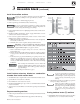
Weil-McLain 80 Boiler For Gas, Light Oil, Gas/Light Oil Fired Burners 9 Install jacket Before installing jacket 1. Packaged boilers • Install top jacket panels per instructions in this manual. 2. Non-packaged boilers • Follow the instructions in this section to install all jacket panels. • Make sure the following are completed before installing jacket: • Boiler hydrostatically pressure-tested. See page 8. • Plugs for unused tappings installed. See control tapping table, page 28 or 29.
• Installation 9 • Start-Up Install jacket Figure 20 Part No.
Weil-McLain 80 Boiler For Gas, Light Oil, Gas/Light Oil Fired Burners 9 Install jacket (continued) Install jacket side panels Install jacket top panels 1. Remove jacket side panels from cartons. 1. Place jacket top panels as shown in Figure 25, page 26. • Remove knockouts for riser pipes or flue outlet using tin snips. 2. Fold out tab in top panel side flange next to top flue knockout to prevent top panel from sagging (see below). 2.
• Installation 9 • Start-Up Install jacket • Maintenance • Parts (continued) Figure 22 Jacket side panel placement — Models 380, 480, 580 and 680 Part No.
Weil-McLain 80 Boiler For Gas, Light Oil, Gas/Light Oil Fired Burners 9 Figure 23 24 Install jacket (continued) Jacket side panel placement — Models 780, 880 and 980 Part No.
• Installation 9 Figure 24 • Start-Up Install jacket • Maintenance • Parts (continued) Jacket side panel placement — Models 1080, 1180, and 1280 Part No.
Weil-McLain 80 Boiler For Gas, Light Oil, Gas/Light Oil Fired Burners 9 Install jacket (continued) Figure 25 Jacket top panel placement 26 Part No.
• Installation 10 • Start-Up • Maintenance • Parts Pipe tankless heaters To pipe tankless heaters: 1. Size piping no smaller than heater inlet and outlet. 2. Automatic mixing valve must be installed. See Figure 26. Follow manufacturer’s instructions to install. 3. Flow regulating valve must be installed. Size according to continuous draw of heater. See Table 10. Follow manufacturer’s instructions to install. 4. Operating control with small adjustable differential scale is recommended.
Weil-McLain 80 Boiler For Gas, Light Oil, Gas/Light Oil Fired Burners 11 Install water boiler controls Install controls: Table 11 Water control tappings (see Figure 27) 1. Install furnished controls where shown in Table 11 and Figure 27. Failure to properly install, pipe and wire boiler controls can result in severe damage to boiler, building and personnel; and is not covered by boiler warranty. 2. Relief valve must be installed with spindle in vertical position. Use fittings provided with boiler.
• Installation 12 • Start-Up • Maintenance • Parts Install steam boiler controls Install controls: Table 12 Steam control tappings (see Figure 28) 1. Install controls where shown in Table 12 and Figure 28. Failure to properly install, pipe and wire boiler controls can result in severe damage to boiler, building and personnel; and is not covered by boiler warranty. a. Install steam pressure operating and high limit controls and pressure gauge. See Figure 28,this page, and Figure 29, page 30.
Weil-McLain 80 Boiler For Gas, Light Oil, Gas/Light Oil Fired Burners 12 Install steam boiler controls Figure 29 Steam control siphon and fittings Figure 30 Water level control locations (see Table 13) 30 Table 13 (continued) Water level control locations Part No.
• Installation 13 • Start-Up • Maintenance • Parts Connect breeching and venting systems General venting information Construct metal breeching: • • • Model 80 boilers operate with positive overfire pressure. Adjust damper assembly (see page 33) during burner start-up to achieve 0.1" W.C. positive pressure at damper sample hole. Select type of venting system Forced draft Boiler, breeching and stub vent operate at positive pressure. Entire system must be gas-tight to prevent leaks.
Weil-McLain 80 Boiler For Gas, Light Oil, Gas/Light Oil Fired Burners 14 Install burner To install burner: 1. Unpack burner. 2. Place gasket around air tube and against burner mounting flange. If sealing rope is used, apply 1/8" continuous bead of rope adhesive around burner mounting flange and apply sealing rope to make gas-tight seal. 3. Mount burner into opening in burner mounting plate. 15 4. Level burner using burner support brackets where required. 5. Secure with furnished bolts. 6.
• Installation 16 • Start-Up • Maintenance • Parts Make final adjustments Figure 35 Flue damper assembly, typical (continued) Determine if water treatment is needed (water boilers only): Do not use petroleum-based cleaning or sealing compounds in boiler system. Severe damage to system components can result, causing substantial property damage. Continual make-up water will reduce boiler life. Minerals can build up in sections, reducing heat transfer, overheating cast iron and causing section failure.
Weil-McLain 80 Boiler For Gas, Light Oil, Gas/Light Oil Fired Burners 17 Dimensions and ratings Notes 1. 2. 3. 4. 5. 6. 7. 8. Burner input based on maximum of 2,000 feet altitude. For higher altitudes consult local Weil-McLain representative. No. 2 fuel oil Commercial Standard Spec. CS75-56. Heat value of oil — 140,000 Btu/Gal. Consult Weil-McLain Burner Specifications and Data Sheet for gas pressures required. MBH refers to thousands of Btu per hour.
• Installation 17 • Start-Up • Maintenance • Parts Dimensions and ratings Part No.
Weil-McLain 80 Boiler For Gas, Light Oil, Gas/Light Oil Fired Burners 18 36 Parts Part No.
• Installation 18 Parts Part No.
Weil-McLain 80 Boiler For Gas, Light Oil, Gas/Light Oil Fired Burners Handling ceramic fiber and fiberglass materials This symbol is used in this addendum to indicate presence of hazards that can cause severe personal injury, death or substantial property damage. REMOVAL OF COMBUSTION CHAMBER LINING OR BASE PANELS The combustion chamber lining or base insulation panels in this product contain ceramic fiber materials. Ceramic fibers can be converted to cristobalite in very high temperature applications.
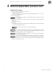
• Installation • Start-Up • Maintenance • Parts Propane boilers — propane gas odorant Propane boilers only — Your propane supplier mixes an odorant with the propane to make its presence detectable. In some instances, the odorant can fade and the gas may no longer have an odor. ■ Propane gas can accumulate at floor level. Smell near the floor for the gas odorant or any unusual odor. If you suspect a leak, do not attempt to light the burner.
Weil-McLain Limited Warranty for Residential & Commercial Cast Iron Boilers ◆ RESIDENTIAL WATER WARRANTY—Limited Lifetime ◆ RESIDENTIAL STEAM WARRANTY—Limited 10 Year ◆ COMMERCIAL WARRANTY—Limited 10-Year These warranties do not cover: 1. Components that are part of the heating systems, but were not furnished by Weil-McLain as a part of the boiler.