WELLS MANUFACTURING COMPANY 2 ERIK CIRCLE, P. O. Box 280 Verdi, NV 89439 Customer Service (775) 345-0444 Ext.502 fax: (775) 345-0569 www.wellsbloomfield.
LIMITED WARRANTY STATEMENT Unless otherwise specified, all commercial cooking equipment manufactured by WELLS MFG. CO. is warranted against defects in materials and workmanship for a period of one year from the date of original installation or 18 months from the date of shipment from our factory, whichever comes first, and is for the benefit of the original purchaser only.
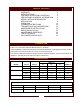
TABLE OF CONTENTS WARRANTY SPECIFICATIONS FEATURES & OPERATING CONTROLS PRECAUTIONS & GENERAL INFORMATION AGENCY LISTING INFORMATION INSTALLATION OPERATION CLEANING INSTRUCTIONS TROUBLESHOOTING SUGGESTIONS MAINTENANCE INSTRUCTIONS MSDS (Ansulex Low pH) MAINTENANCE SCHEDULES PARTS & SERVICE CUSTOMER SERVICE DATA xi 1 2 6 7 8 13 18 22 23 26 28 31 31 INTRODUCTION Thank You for purchasing this Wells Manufacturing Co. appliance.
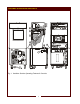
FEATURES & OPERATING CONTROLS Fig.
FEATURES & OPERATING CONTROLS (continued) VENTILATOR SECTION ITEM DESCRIPTION COMMENT 1. NAMEPLATE Gives Manufacturer, Model and Serial Number information. Also lists electrical specifications. a6. FIRE SUPPRESSION AGENT TANK (1.5 gal.) Container for Ansulex™ Low-pH liquid fire suppression liquid. 8. ADJUSTABLE (FRONT) LEG Allows the unit to be leveled. 9. RIGID (REAR) CASTER Allows the unit to be easily positioned by lifting the front of the unit slightly. a10.
FEATURES & OPERATING CONTROLS (continued) V1 V2 V3 V4 Fig. 2 Ventilator Section Controls & Indicator Lights Fig. 3 Cooktop Section Controls & Indicator Lights Fig.
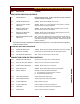
FEATURES & OPERATING CONTROLS (continued) ITEM DESCRIPTION COMMENT VENTILATOR SECTION CONTROLS V1 POWER SWITCH Energizes blower motor. If, after 10 seconds, proper conditions are met, cooktop is energized. V2 POWER ON INDICATOR GREEN. Glows when POWER switch is ON. V3 CHECK FILTERS ALARM INDICATOR AMBER. Glows if one or more filters are out of position. Check all filters and baffles for proper installation. V4* REPLACE PREFILTER ALARM INDICATOR AMBER.
PRECAUTIONS AND GENERAL INFORMATION WARNING: Electric Shock hazard All servicing requiring access to non-insulated electrical components must be performed by a factory authorized technician. DO NOT open any access panel which requires the use of tools. Failure to follow this warning can result in severe electrical shock. CAUTION: Risk of Damage DO NOT connect or energize this appliance until all installation instructions are read and followed.
PRECAUTIONS AND GENERAL INFORMATION (continued) OPERATIONAL NOTES: REPLACE PREFILTER and REPLACE FILTER PACK indicator lights provide a timely warning that a system shut-down is imminent. The actual time between the indicator light coming on and the loss of cooking appliance power will depend upon the cooking conditions. Anytime a dirty PRE-FILTER is replaced, the system airflow will increase. If the condition of the FILTER PACK is marginal, the REPLACE FILTER PACK light could then come on.
INSTALLATION NOTE: DO NOT discard the carton or other packing materials until you have inspected the appliance for hidden damage and tested it for proper operation. Refer to SHIPPING DAMAGE CLAIM PROCEDURE on the inside front cover of this manual. WARNING: Risk of personal injury Installation procedures must be performed by a qualified technician with full knowledge of all applicable electrical codes. Failure can result in personal injury and property damage.
INSTALLATION (continued) SERVICE TECHNICIAN INSTALLATION NOTES An Ansul® technician must charge and arm the fire suppression system before the ventilator blower will operate. See page 10. Installation and start up must be performed by an Authorized Installation Company. Installer must complete the WARRANTY REGISTRATION form, and record appliance installation particulars on the CUSTOMER SERVICE DATA form in this manual. Certain codes require cooking equipment to be restrained with a RESTRAINT DEVICE.
INSTALLATION (continued) DANGER FIRE HAZARD FIRE SUPPRESSION SYSTEM INSTALLATION 1. Any REMOTE MANUAL PULL STATION must be installed by an authorized ANSUL® distributor in accordance with the AUTHORITY HAVING JURISDICTION. NOTE: If a REMOTE MANUAL PULL STATION is installed, moving the unit for servicing will cause the Ansul® system to discharge. In this case, the unit must only be installed with four fixed legs (i.e. remove rear casters and replace with legs).
INSTALLATION (continued) FILTERS INSTALLATION 1. FILTER PACK: Ships installed in the hood. If the FILTER PACK is not in position, the CHECK FILTERS indicator will light. If the FILTER PACK becomes clogged, the REPLACE FILTER PACK indicator will glow. To install the FILTER PACK: Position the filter pack with the charcoal portion UP. Slide the filter pack toward the rear of the unit until it contacts the guides on the back panel.
INSTALLATION (continued) WARNING Slipping / Falling Hazard Spilled Oil GREASE TROUGH AND GREASE CUP INSTALLATION 1. Install the GREASE TROUGH into the brackets below the grease baffle. 2. Install the GREASE CUP on the right side of the unit, directly below the grease trough. HOTPLATE DRIP PAN INSTALLATION (SPIRAL HEATING ELEMENTS ONLY) 1. Lift / rotate the elements up. DO NOT OPERATE UNLESS THE GREASE CUP IS INSTALLED. Oil and moisture will drip onto the floor and falls may result.
OPERATION CAUTION: VENTILATOR OPERATION 1. Press the VENTILATOR POWER switch to ON. The green VENTILATOR POWER light will glow and the blower fan will start. After a short time, if all filters are sensed as being in position and not clogged, the cooking appliance will be energized. The roll warmer is energized at all times. During normal operation, the VENTILATOR POWER light will be the only light glowing on the upper control panel. Hot Surface Exposed surfaces can be hot to the touch and may cause burns.
OPERATION (continued) SUGGESTED COOKING TIMES A. CONVECTION OVEN PRODUCT TEMP ºF TIME MINUTES NUMBER OF RACKS BREAD PRODUCTS Hamburger Roll 300 15 5 Bread (1 lb loaves) 325 34 3 (12 loaves) Roll 300 16 5 (60 rolls) Baking Soda Biscuit 400 7 3 For best baking results, use rack positions 2, 5 & 8 ( where rack position 1 is the top rack) Baking one pan: use rack 5; baking 2 pans: use racks 2 & 8. PASTRIES Sheet Cake (2½ lbs. per pan) Frozen Fruit Pie (46oz.) Frozen Fruit Pie (26oz. - 8" dia.
OPERATION (continued) CONVECTION OVEN OPERATING INSTRUCTIONS CAUTION: Hot Surface A. MANUAL COOK MODE 1. Set the OVEN POWER SWITCH (C.01) to ON. The OVEN POWER ON INDICATOR (C.03) will glow when the switch is ON. 2. Rotate OVEN TEMPERATURE CONTROL knob (C.07) until the desired cooking temperature is displayed on the READOUT (C.05A). The oven will begin heating, and the temperature digits will flash, until the set temperature is reached. 3. Rotate OVEN TIME CONTROL knob (C.
OPERATION (continued) CAUTION: C. TEMPERATURE OFFSET MODE Hot Surface 1. A user preference offset mode is provided should the user feel the oven cooks too hot or too cold. Exposed surfaces can be hot to the touch and may cause burns. CAUTION: Burn Hazard Do not attempt to clean the oven until it has cooled to 150ºF or less. See CLEANING INSTRUCTIONS, page 18. 2. The OFFSET MODE can be used to offset the set / displayed temperature from the sensed temperature by as much as ± 35ºF, in 5ºF increments: a.
OPERATION (continued) HOTPLATE OPERATING INSTRUCTIONS CAUTION: Hot Surface A. COOKING WITH YOUR HOTPLATE 1. Each element is individually controlled by a TEMPERATURE CONTROL (H.01 and H.03). These are infinite switch controls which control based on electrical current draw, not the actual temperature of the hotplate surface. Exposed surfaces can be hot to the touch and may cause burns. CAUTION: 2. Settings are OFF to HIGH. Electrical Shock Hazard DO NOT splash or pour water onto control panel or wiring.
CLEANING INSTRUCTIONS DANGER ELECTRIC SHOCK HAZARD CONVECTION OVEN CLEANING INSTRUCTIONS PRECAUTIONS Turn oven power switch to FAN Allow oven to cool FREQUENCY As Noted TOOLS Mild Detergent, Soft Cloth or Sponge Plastic Scouring Pad Spray Bottle Commercial Oven Cleaner/Degreaser DAILY DO NOT SPRAY WATER ON OR AROUND ELECTRICAL EQUIPMENT DO NOT WASH FLOOR NEAR ELECTRICAL EQUIPMENT WITH WATER SPRAY 1. Turn oven power switch to FAN; remove racks and take to back sink. 2. Let oven cool to 200°F.
CLEANING INSTRUCTIONS (continued) HOTPLATE CLEANING INSTRUCTIONS CAUTION: Burn Hazard PRECAUTIONS Turn oven controls to OFF Allow hotplates to cool FREQUENCY Daily TOOLS Mild Detergent, Soft Cloth or Sponge Non-abrasive Cleaner, Plastic Scouring Pad Turn off both hotplates and allow to cool before cleaning 1. Turn both controls to OFF. Allow both hotplate elements to cool. 2. Wipe the entire hotplate top panel using a clean cloth or sponge, dampened with hot water and a mild detergent.
CLEANING INSTRUCTIONS (continued) CAUTION: Electric Shock Hazard Disconnect appliance from electric power before cleaning. CAUTION: Hot Surface Exposed surfaces can be hot to the touch and may cause burns. Allow appliance to cool before cleaning. IMPORTANT: Never allow PRE-FILTER or FILTER PACK to get wet. DO NOT wash either of these two filters. Washing these filters will ruin them and cause the appliance to shut-down.
TROUBLESHOOTING SUGGESTIONS A. NO PART OF THE APPLIANCE WILL HEAT CAUTION: 1. Verify that appropriate cooking controls are ON. 2. Check electrical supply. Make sure service breaker is ON. 3. Make sure all filters are properly installed, and that no filter warning lights are lit. 4. Possible improper service wiring: Have a licensed electrician verify that all three legs of the 3ø service are properly connected (i.e.
MAINTENANCE INSTRUCTIONS A. FAN CLEANING CAUTION: 1. Disconnect power at the circuit breaker. Allow the oven to cool. Personal Injury Hazard 2. Remove RACKS by pulling toward the front. Lift to clear the stop pin. Remove left and right RACK SUPPORTS by lifting. 3. Remove BAFFLE by lifting the rear slightly and pulling straight out. 4. Brush fan wheel and wipe it with a moist cloth. Sponge out all loose particles.
MAINTENANCE INSTRUCTIONS (continued) C. HINGE ADJUSTMENT 3. The door should be approximately centered between the upper and lower lips of the cabinet. Adjust the door for height: a. The hinge sleeve acts as a jam nut for the height adjuster. b. The top and bottom clearances should be approximately equal. If necessary, loosen the hinge sleeve and turn the height adjustment nut until the required clearances are achieved. c. Retighten the hinge sleeve. 4.
MAINTENANCE INSTRUCTIONS (continued) CAUTION: Hot Surface Exposed surfaces can be hot to the touch and may cause burns. D. TEMPERATURE CALIBRATION TOOLS: Digital Pyrometer with Oven Probe, Protective Gloves 1. With the oven empty, clamp the thermocouple sensor in the center of the middle rack: a. Pass the thermocouple sensor wires through the corner of the door gasket and close the door. b. Plug the sensor into the Pyrometer. 2. Turn the OVEN POWER (V.01) switch to ON. Turn the FAN switch (V.02) to HI.
MAINTENANCE SCHEDULES 1. 6-MONTH MAINTENANCE (MUST BE PERFORMED BY AN AUTHORIZED ANSUL® DISTRIBUTOR ONLY): a. Inspect and test total operation including FIRE DAMPER and all SAFETY INTERLOCKS. b. All FIRE SUPPRESSION SYSTEM actuation components including MANUAL PULL STATION and any REMOTE MANUAL PULL STATION must be inspected for proper operation in accordance with the maintenance schedule published in ANSUL® R-102 SYSTEM DESIGN, INSTALLATION, RECHARGE AND MAINTENANCE MANUAL (Ansul® #418087-05). c.
26
27
ANSUL® MATERIAL SAFETY DATA SHEET ANSUL INCORPORATED MARINETTE, WI 54143-2542 ANSULEX Low pH QUICK IDENTIFIER (In Plant Common Name) Manufacturer’s Name: ANSUL INCORPORATED Emergency Telephone No.
ANSULEX Low pH (continued) SECTION 5 - HEALTH HAZARDS Threshold Limit Value: None Established Routes of Entry: Eye Contact: Irritant Skin Contact: Irritant Inhalation: Not an expected route of entry. Can be irritating to mucous membranes. Ingestion: Irritating to mucous membranes. Acute Oral LD50 (Sprague-Dawley rats) 825.5mg/kg. Acute Exposure: Material irritates skin, eyes, and mucous membranes. Chronic Exposure: None known.
NOTES 24
PARTS & SERVICE DESCRIPTION OVEN RACK Replacement PRE-FILTER PRE-FILTER CAGE FILTER PACK (HEPA + CHARCOAL) GREASE BAFFLE GREASE CUP LEG KIT CASTER KIT DRIP TRAY, 8” (Spiral Hotplate) SCRAPER, CLEANING (Ceramic Hotplate) ELEMENT SUPPORT (Spiral Hotplate) CLEANING CREME, CERAMIC HOTPLATE SERVICE PART NO. WELLS BULLETIN (ANSUL® PARTS LIST) NOTE: Ansul® Manual 418087-05 and Wells Bulletin 303331 are intended for use by authorized Ansul® service personnel only.