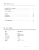
Table of Contents Technical data………………………………………………………………………………. 2 General safety rules………………………………………………………………………... 3 Specific safety rules for the drill press…………………………………………………… 5 Electrical information………………………………………………………………………. 6 Know your drill press………………………………………………………………………. 8 Assembly and adjustments……………………………………………………………….. 9 Operation……………………………………………………………………………………. 16 Maintenance………………………………………………………………………………… 17 Troubleshooting……………………………………………………………………………..
General safety rules Safety is a combination of common sense, staying alert, and knowing how your drill press works. SAVE THESE SAFETY INSTRUCTIONS. WARNING: To avoid mistakes that could cause serious injury, do not plug in the drill press until the following steps have been read and understood. 1. READ and become familiar with this entire instruction manual. LEARN the tool’s applications, limitations, and possible hazards. 2. AVOID DANGEROUS CONDITIONS.
General safety rules (continued) 13. NEVER LEAVE A RUNNING TOOL UNATTENDED. Turn the power switch to OFF. Do not leave the tool until it has come to a complete stop. 14. NEVER STAND ON A TOOL. Serious injury could result if the tool tips or is accidentally hit. DO NOT store anything above or near the tool. 15. DO NOT OVERREACH. Keep proper footing and balance at all times. Wear oil-resistant rubbersoled footwear. Keep the floor clear of oil, scrap, and other debris. 16. MAINTAIN TOOLS PROPERLY.
Specific safety rules for the drill press WARNING: Do not operate the drill press until it is completely assembled and installed according to the instructions. 1. Never turn the drill press on until the table is clear of all foreign objects (tools, scraps, etc.). 2. Always keep hands and fingers away from the drill bit. 3. Do not drill materials that do not have a flat surface—unless a suitable support is used (clamp or vise). 4. Never start the drill press with the drill bit pressed against the workpiece.
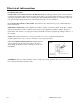
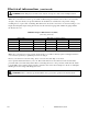
Electrical information Grounding instructions IN THE EVENT OF A MALFUNCTION OR BREAKDOWN, grounding provides the path of least resistance for electric current and reduces the risk of electric shock. This tool is equipped with an electric cord that has an equipment grounding conductor and a grounding plug. The plug MUST be plugged into a matching outlet that is properly installed and grounded in accordance with ALL local codes and ordinances. DO NOT MODIFY THE PLUG PROVIDED.
Electrical information (continued) WARNING: This drill press is for indoor use only. Do not expose to rain or use in damp locations. Guidelines for using extension cords Make sure your extension cord is in good condition. When using an extension cord, be sure to use one heavy enough to carry the current your product will draw. An undersized cord will cause a drop in line voltage resulting in loss of power and overheating.
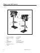
Know your drill press Fig. 1 1 Speed control handle 2 Support lock handle 9 Feed handle 10 Column 3 Table 4 Base 11 Rack 12 Crank handle 5 ON/OFF Switch 13 Housing cover screw 6 Safety key 14 Laser ON/OFF switch 7 Digital speed readout 8 Chuck 4212 8 WENPRODUCTS.
Assembly and adjustments Unpacking Unpack the drill press and all its parts, and compare against the list below. Do not discard the carton or any packaging until the drill press is completely assembled. To protect the drill press from moisture, a protective coating has been applied to the machined surfaces. Remove this coating with a soft cloth moistened with kerosene or WD-40®. Do not use acetone, gasoline, or lacquer thinner to clean. Apply a coat of good paste wax to the table and column.
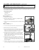
Assembly and adjustments (continued) WARNING: If any part is missing or damaged, do not plug the drill press in until the missing or damaged part is repaired or replaced, and assembly is complete. The column assembly (column, column support, rack, rack collar, and table support bracket) must be attached to the base. The table and table support handles must be attached to the table support bracket. The motor housing must be attached to the column.
Assembly and adjustments (continued) Note: Make sure there is enough clearance to allow the table to rotate around the column. The collar must sit loosely over rack and not angled on the column. To avoid column or collar damage, only tighten the set screw enough to keep collar in place (Fig. 3). Fig. 5 7. Insert the table support crank handle (9) into the worm gear shaft on the side of the table support (8).
Assembly and adjustments (continued) Speed handle (Fig. 8) 1. Insert the feed handle (1) into the threaded opening on the speed hub (2). 2. Manually tighten handle into opening. Warning: Do not change speed without turn on the machine. 2 Fig. 8 1 Mount the drill press (Fig. 9) The drill press must be securely fastened through the mounting holes (1) to a stand or workbench with heavy duty fasteners. This will prevent the drill press from tipping over, sliding, or walking during operation.
Assembly and adjustments (continued) Table adjustments Fig. 11 Raise or lower the table (Fig. 11) 1. Loosen the support lock handle (1) and turn the crank handle (2) until the table is at the desired height. 1 2 2. Tighten the support lock handle (1) before drilling. Rotate the table (Fig. 11) 1. Loosen the support lock handle (1) and turn the table around the column to the desired position. Note: The rack should rotate around the column with the table support bracket.
Assembly and adjustments (continued) Laser batteries (Fig. 13) Fig. 13 1. Turn off the laser. 3 2. Press the tab (1) located below the laser switch (2) and lift up the laser switch cover (3). 2 3. Insert 2 "AA" batteries in the laser battery compartment. 4. Close the laser switch cover. 1 Laser line (Fig. 14) WARNING: Do not stare directly at the laser beam! A hazard may exist if you deliberately stare into the beam. Please observe all safety rules.
Assembly and adjustments (continued) Spindle return spring (Fig. 15) The spindle is equipped with an auto-return mechanism. The main components are a spring and a notched housing. The spring was properly adjusted at the factory and should not be readjusted unless absolutely necessary. 1. Unplug the drill press. 2. Place a screwdriver into the loop (1) to hold the spring in place. 3. Loosen the two housing nuts (3) approximately 1/4" (6 mm). Do not remove the nuts from the threaded shaft.
Operation Drill Press ON/OFF switch (Fig. 17) 1. To turn the drill press ON, insert the yellow safety key (1) into the switch housing. As a safety feature, the switch cannot be turned ON without the safety key. Fig. 17 2 1 2. Flip the switch (2) upward to the ON position. 3. To turn the drill press OFF, press the switch downward. 4. To lock the switch in the OFF position, remove the safety key (1) from the switch. Store the safety key in a safe place.
Operation (continued) Drilling speeds Important factors when determining the best drilling speed: Material type Hole size Drill bit or cutter type Quality desired Smaller drill bits require greater speed than large drill bits. Softer materials require greater speed than harder materials. See page 23 for recommended speeds for the workpiece material. Drilling metal Use metal-piercing twist drill bits.
Operation (continued) Mechanical variable speed (Fig. 18) Fig. 18 2 This is a mechanical variable speed drill press. To increase or decrease the speed when operating, raise or lower the speed handle (1). Use the following table to determine the recommended speed for the drill size you are using and the type of material you are to drill. While drilling, check the speed on the digital speed readout (2) located at the front of the drill press. 1 Warning: Do not change speed without turn on the machine.
Maintenance WARNING: For your safety, turn the switch off and remove the plug from the power supply before maintaining or lubricating the drill press. Vacuum sawdust or metal shavings that accumulates in and on the motor, pulley housing, table, and work surface. Apply a light coat of paste wax to the column and table to help keep these surfaces clean and rust- free. The ball bearings in the spindle and the V-belt pulley assembly are greased and permanently sealed.
Troubleshooting PROBLEM PROBABLE CAUSE REMEDY Noisy operation 1. Incorrect belt tension. • Adjust the belt tension. See To replace the belt in Adjustments. Lubricate the spindle. See Maintenance. • Tighten the retaining nut on the pulley insert. • Tighten the set screw on the side of the motor pulley. 2. Dry spindle. 3. Loose spindle pulley. 4. Loose motor pulley. The drill bit burns or smokes. 1. Drilling at the incorrect speed. 2. The wood chips are not coming out of the hole. 3. Dull drill bit.
Troubleshooting 4212 (continued) PROBLEM PROBABLE CAUSE REMEDY The workpiece splinters on the underside. 1. No backup material under the workpiece. • Always use a backup material. See Position the table and workpiece in Operation. The workpiece is slipping from your hand. 1. Not supported or clamped properly. • Support workpiece using extension wing or clamps. See Position the table and workpiece in Operation. Motor will not run. • Take to a qualified service technician. 1.
Replacement parts Service Information Now that you have purchased your bench top power tool, should a need ever exist for service, simply call Great Lakes Technologies, LLC Service Department at (800) 232-1195 M-F 8-5 CST. Be sure to provide all pertinent facts when you call or visit. Replacement Parts Use only WEN® replacement parts. Use of any other parts may cause damage to your machine. When ordering replacement parts, please provide the model number, part number, and description.
Parts list Item Stock # Item Stock # 1 4212-001 Column Description 41 4212-041 Knob Description 2 4212-002 Rack 44 4212-044 Screw M8x25 3 4212-003 Column support 45 4212-045 Washer 4 4212-004 Base 46 4212-046 Retaining plate 5 4212-005 Screw M8x20 47 4212-047 Screw M8x12 6 4212-006 Crank handle 48 4212-048 Motor cable 7 4212-007 Pin 49 4212-049 Nut M8 8 4212-008 Screw M12x25 50 4212-050 Motor 9 4212-009 Table 51 4212-051 Gasket 10 4212-010 Table
Parts list 4212 (continued) Item Stock # Item Stock # 86 4212-086 Sleeve Description 97 4212-097 Screw M8x8 87 4212-087 Power cord 98 4212-098 Plain key 88 4212-088 Nut M12 99 4212-099 Speed handle 89 4212-089 Spring cover 100 4212-100 Knob 90 4212-090 Screw M5x12 101 4212-101 Coil spring 91 4212-091 Nut M10 102 4212-102 Compressed spring tool 92 4212-092 Split washer 103 4212-103 Nut M8 93 4212-093 Hub 104 4212-104 Screw 94 4212-094 Fixing plate 105
Exploded view 4212 25 WENPRODUCTS.
Two years limited warranty ® WEN is committed to building tools that are dependable for years. Our warranties are consistent with our commitment and dedication to quality. TWO (2) YEARS LIMITED WARRANTY OF WEN PRODUCTS FOR HOME USE. GREAT LAKES TECHNOLOGIES, LLC (“Seller") warrants to the original purchaser only, that all WEN consumer power tools will be free from defects in material or workmanship for a period of two (2) years from date of purchase.
4212 27 WENPRODUCTS.