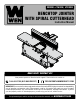
MODEL JT630H, JT833H BENCHTOP JOINTER WITH SPIRAL CUTTERHEAD Instruction Manual NEED HELP? CONTACT US! Have product questions? Need technical support? Please feel free to contact us: 1-800-232-1195 (M-F 8AM-5PM CST) TECHSUPPORT@WENPRODUCTS.COM IMPORTANT: Your new tool has been engineered and manufactured to WEN’s highest standards for dependability, ease of operation, and operator safety. When properly cared for, this product will supply you years of rugged, trouble-free performance.
CONTENTS WELCOME 3 Introduction...................................................................................................... 3 Specifications.................................................................................................... 3 SAFETY 4 General Safety Rules......................................................................................... 4 Jointer Safety Warnings.................................................................................... 6 Electrical Information.
INTRODUCTION Thanks for purchasing the WEN Benchtop Jointer. We know you are excited to put your tool to work, but first, please take a moment to read through the manual. Safe operation of this tool requires that you read and understand this operator’s manual and all the labels affixed to the tool. This manual provides information regarding potential safety concerns, as well as helpful assembly and operating instructions for your tool. Indicates danger, warning, or caution.
GENERAL SAFETY RULES WARNING! Read all safety warnings and all instructions. Failure to follow the warnings and instructions may result in electric shock, fire and/or serious injury. Safety is a combination of common sense, staying alert and knowing how your item works. The term “power tool” in the warnings refers to your mains-operated (corded) power tool or battery-operated (cordless) power tool. SAVE THESE SAFETY INSTRUCTIONS. WORK AREA SAFETY 1. Keep work area clean and well lit.
GENERAL SAFETY RULES WARNING! Read all safety warnings and all instructions. Failure to follow the warnings and instructions may result in electric shock, fire and/or serious injury. Safety is a combination of common sense, staying alert and knowing how your item works. The term “power tool” in the warnings refers to your mains-operated (corded) power tool or battery-operated (cordless) power tool. SAVE THESE SAFETY INSTRUCTIONS. 7.
JOINTER SAFETY WARNINGS WARNING! Do not let comfort or familiarity with the product replace strict adherence to product safety rules. Failure to follow the safety instructions may result in serious personal injury. JOINTER SAFETY 1. TOOL PURPOSE This jointer is designed for creating flat surfaces on wood or wood-like products only. Smoothing other materials could result in fire, injury, or damage to the workpiece.
JOINTER SAFETY WARNINGS WARNING! Do not let comfort or familiarity with the product replace strict adherence to product safety rules. Failure to follow the safety instructions may result in serious personal injury. 19. Never perform layout, assembly or set-up work on the table while the jointer is operating. 20. Always turn off and unplug the machine before cleaning, making adjustments or changing attachments.
ELECTRICAL INFORMATION GROUNDING INSTRUCTIONS In the event of a malfunction or breakdown, grounding provides the path of least resistance for an electric current and reduces the risk of electric shock. This tool is equipped with an electric cord that has an equipment grounding conductor and a grounding plug. The plug MUST be plugged into a matching outlet that is properly installed and grounded in accordance with ALL local codes and ordinances. 1. Do not modify the plug provided.
UNPACKING & PACKING LIST UNPACKING With the help of a friend or trustworthy foe, such as one of your in-laws, carefully remove the jointer from the packaging and place it on a sturdy, flat surface. Make sure to take out all contents and accessories. Do not discard the packaging until everything is removed. Check the packing list below to make sure you have all of the parts and accessories.
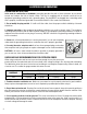
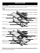
KNOW YOUR JOINTER TOOL PURPOSE Resurface boards, flatten workpieces, and much more with your WEN Jointer. Refer to the diagram below to become familiarized with the parts and controls of your jointer.
ASSEMBLY & ADJUSTMENTS ATTACH THE FENCE Fig. 2 1 1. Attach the fence support bracket (Fig. 2 - 1) to the jointer with four socket head bolts (Fig. 2 - 2) 2. Assemble the fence sliding bracket (Fig. 3 - 1) to the fence (Fig. 3 - 2). Insert the two socket head bolts (Fig. 3 - 3) through the top of the fence sliding bracket and screw the square nuts (Fig. 3 - 4) onto the bolts but do not tighten. 2 3.
ASSEMBLY & ADJUSTMENTS ADJUST THE TABLE SUPPORTS Fig. 6 The 8” jointer, JT833H, is equipped with a extendable table supports (Fig. 6 - 1). To extend the supports, loosen the two knobs (Fig. 6 - 2) on each side of the support bar and reposition the support to the desired position. Once the support is in the desired position, re-tighten the knobs underneath the table. ADJUST AND LEVEL THE TABLE 1 The infeed and outfeed table have been pre-set at the factory to be level and in line with the blades.
ASSEMBLY & ADJUSTMENTS ADJUST AND LEVEL THE TABLE (CONT.) 6. When both the infeed and outfeed tables are aligned with the blades, lay the straightedge across the infeed and outfeed tables to ensure that they are level. If the tables are not perfectly aligned, tune the outfeed table to the infeed table using step 4 above to adjust the level of the table. WARNING! Do not plug in or turn on the tool until it is fully assembled according to these instructions.
ASSEMBLY & ADJUSTMENTS MOVE THE FENCE Fig. 10 1. Before adjusting the fence’s position, make sure that the unit is unplugged and the power switch is in the OFF position. 2. Loosen the fence sliding handle (Fig. 10 - 1). 3. Slide the fence to the desired position. The fence can be positioned over the blade so that only the desired width of the blade is exposed. Make sure the exposed width matches that of the workpiece. 1 2 4. Tighten the fence sliding handle so that the fence is secure.
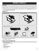
OPERATION 4. Cut with the grain whenever possible (Fig. 14). Do not feed against the end grain (Fig. 15), otherwise the workpiece may split and shatter. If the nature of the workpiece requires you to joint against the grain, take extremely light cuts and feed slowly. When using long work pieces, use extra supports at both ends of the jointer. Fig. 14 FEED With the Grain BEVEL AND CHAMFER Rotation The fence on the jointer is adjustable from 0° to 45°.
MAINTENANCE WARNING! To avoid accidents, turn OFF and unplug the tool from the electrical outlet before cleaning, adjusting, or performing any maintenance or lubrication work. WARNING! Any attempt to repair or replace electrical parts on this tool may be hazardous. Servicing of the tool must be performed by a qualified technician. When servicing, use only identical WEN replacement parts. Use of other parts may be hazardous or induce product failure.
MAINTENANCE WARNING! To avoid cuts, wear cut-proof or cut-resistant gloves when performing maintenance work on the blades. Remove the gloves before operating the jointer. REPLACING OR ROTATING BLADES Your jointer is equipped with a helical cutting head consisting of 12 blades. Each blade is indexed with a small dot in the corner to denote the two sharp sides of the blade. Once a side of the blade is dull or nicked, use the star head wrench to remove the retaining screw to rotate or replace the blade.
TROUBLESHOOTING GUIDE WARNING! Stop using the tool immediately if any of the following problems occur. Repairs and replacements should only be performed by an authorized technician. For any questions, please contact our customer service at 1-(800) 232-1195, M-F 8-5 CST or email us at techsupport@wenproducts.com. PROBLEM CAUSE Jointer is not plugged in. Plug jointer in. Wrong choice of extension cord. Choose proper size of extension cord. Defective switch. Motor does not start. Defective motor.
EXPLODED VIEW & PARTS LIST JT630H 133S 24 135S 24 131 132 136 131 128 130 139(2) 137 126 130a 129(2) 139(4) 46(8) 43a(8) 166 125 71 72 70(2) 102 43(2) 140 160_S 101_S 6(3) 39 162(12) 163(12) 3 4(4) 6(2) 6 36_S 6(3) 41 138(3) 40 6(2) 48(16) 319(2) 50 34 13 5 8 51_S 9 6(2) 300S 7(2) 6(2) 10 28a(4) 26 35(4) 29 323a 6(3) 27b(2) 27a(2) 14_S 11 28(4) 17 6 7(2) 20 324 21 62 12 22 49(8) 27(2) 64 23 25(4) 323 24 23 19
EXPLODED VIEW & PARTS LIST JT630H No. 3 4 5 Part No. JT630H-003 JT630H-004 JT630H-005 6 JT630H-006 7 JT630H-007 8 9 10 12 13 JT630H-008 JT630H-009 JT630H-010 JT630H-012 JT630H-013 JT630HBearing Retainer Assy. 014ASM JT630H-017 C-Ring JT630H-020 Pointer JT630H-021 Gear JT630H-022 Scale JT630H-023 Lock Knob M8 JT630H-024 M8 Flat Washer JT630H-025 Foot JT630H-026 Ext Retaining Ring JT630H-027 Screw M5-0.8x8 JT630HLock Washer 027A JT630HHex Nut M5 027B JT630H-028 Screw M5-0.
EXPLODED VIEW & PARTS LIST JT630H No. 319 320 321 Part No. JT630H-319 JT630H-320 JT630H-321 Description Brush Holder Carbon Brush Brush Cover Qty. 2 2 2 No. 323 323a 324 Part No. JT630H-323 JT630H323A JT630H-324 Description Switch Qty.
EXPLODED VIEW & PARTS LIST JT833H 37 71 72 70(2) 6(3) 44 35(2) 17 14_S 6(2) 12 7(2) 48(8) 110 6 10 13 49(8) 112 23 5 3 323a 24 21 26 25(2) 8 33 30A 6(2) 32 9 115 45 30_S 51_S 102_S 1_S (2) 64 34 23 2 6(2) 7(2) 111 125 36_S 50 39 114 40 129 41 130 128 6(3) 6 131(2) 35(2) 6(2) 48(8) 25(2) 319(2) 132 300S 136 24 133S 137 24 130a 135S 22
EXPLODED VIEW & PARTS LIST JT833H No. 1_S 2 3 4 5 6 7 8 9 10 12 13 14_S 17 20 21 23 24 25 26 27 27a 27b 28 28a 29 30_S 32 33 34 35 36_S Part No. Description Qty. JT833HTable Assy. 2 001ASM JT833H-002 Right Cover 1 JT630H-003 Outfeed Support 1 JT630H-004 Set Screw M6x8 8 JT833H-005 Left Cover 1 JT630H-006 Screw M6x12 16 JT630H-007 Screw 4 JT833H-008 Dust Chute 1 JT833H-009 Cutter Head Foam Seal 1 JT833H-010 Front Foam Seal 1 JT630H-012 Front Frame 1 JT833H-013 Dust Port 1 JT630HBearing Retainer Assy.
EXPLODED VIEW & PARTS LIST JT833H No. 300S 319 320 321 24 Part No. JT630H300ASM JT630H-319 JT630H-320 JT630H-321 Description Qty. Motor Assy. 1 Brush Holder Carbon Brush Brush Cover 2 2 2 No. 323 323a 324 Part No. JT630H-323 JT630H323A JT630H-324 Description Switch Qty.
WARRANTY STATEMENT WEN Products is committed to building tools that are dependable for years. Our warranties are consistent with this commitment and our dedication to quality. LIMITED WARRANTY OF WEN PRODUCTS FOR HOME USE GREAT LAKES TECHNOLOGIES, LLC (“Seller”) warrants to the original purchaser only, that all WEN consumer power tools will be free from defects in material or workmanship during personal use for a period of two (2) years used for professional or commercial use.
NOTES 26
NOTES 27
THANKS FOR REMEMBERING V. 2022.01.