PMA Prozeß- und Maschinen-Automation GmbH Industrial controller KS 50-1and KS 52-1 KS50-1 KS52-1 KS50-1 KS52-1 Operating manual English 9499-040-62811 Valid from: 07/2011
û BlueControl More efficiency in engineering, more overview in operating: The projecting environment for the BluePort® controllers ! on N O es I d a t de T . E N U p ine T and onl CD T A are ma- A- w w.p n PM t f So ww or o Description of symbols in the text: on the device: g General information a Follow the operating instructions a General warning l Attention: ESD-sensitive devices © PMA Prozeß- und Maschinen-Automation GmbH • Printed in Germany All rights reserved.
Contents 1 2 2.1 2.2 2.3 3 3.1 3.2 3.3 3.4 3.5 3.5.1 3.5.2 3.5.3 3.5.4 3.5.5 3.5.6 3.5.7 3.5.8 3.6 3.7 3.8 3.9 4 4.1 4.2 4.3 Mounting . . . . . . . . . . . . . . . . . . . . . . . . . . . . . . 5 Electrical connections . . . . . . . . . . . . . . . . . . . . . . . 7 Connecting diagram. . . . . . . . . . . . . . . . . . . . . . . . . 7 Connecting diagram for the options card . . . . . . . . . . . . . . 8 Terminal connection . . . . . . . . . . . . . . . . . . . . . . . . 8 Operation . . . . . . . . . . . .
.4.2 4.4.3 4.4.4 Switching attitude linear ( CyCl= 1 ) . . . . . . . . . . . . . . . . 39 Switching attitude non-linear ( CyCl= 2 ) . . . . . . . . . . . . . . 39 Heating and cooling with constant period ( CyCl= 3 ) . . . . . . . . 40 4.5 Configuration examples . . . . . . . . . . . . . . . . . . . . . . 41 4.5.1 4.5.2 4.5.3 4.5.4 4.5.5 4.5.6 5 5.1 5.2 5.3 On-Off controller / Signaller (inverse) . . . . . . . . . . . . 2-point and continuous controller (inverse) . . . . . . . . . .
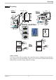
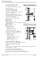
Mounting 1 Mounting .4 +0,8 1 2 3 OK SP.x run Ada Err 96 (3.78") 96 ( 92 1 18 ) 5" 6 4. (0 1. .0 .1 4. 0 .0 .4 ") 10 (0 92 +0,8 KS 52-1 (3.62" +0.03) ") min.48 (1.89") 92 +0,8 KS 50-1 SP.X 126 125 45 run Ada (1.77" Err è 48 (1.89") +0,6 +0.02 8 11 10 ) Safety switches UiI 10V i mA/Pt 96 max. 60°C min. 0°C max. 95% rel. % Loc Ü Ü oder: * * Safety switch: For access to the safety switches, the controller must be withdrawn from the housing.
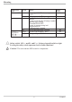
Mounting Name of safety Position switch 10V i mA/Pt right Loc left open close U<-> I right (I) only valid for KS5.-1.4-.....-... left (U) KS5.-1.5-.....-... Remark Current signal / Pt100 / thermocouple at InP.1 Voltage signal at InP.1 Levels as set using the BlueControl®eng.
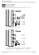
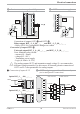
Electrical connections 2 Electrical connections 2.1 Connecting diagram Electrical connections for all types KS 5x-1 exept KS 5_-1_4-_ 00_ _-_ _ 1 2 90...250V 24V AC/DC L N 3 4 N/O 5 C 6 N/O 7 C OUT1 OUT2 KS 5_-1.2-.....-... KS 5_-1.3-.....-... Logic 8 N/C 9 N/O OUT3 U 10 HC mA 11 12 INP2 di1 13 mA 14 0..10 V INP1 15 a b c d Electrical connections for KS 5_-1_4-_____-__ 1 2 90...
Electrical connections 2.2 Connecting diagram for the options card Option KS5_-1..-8....-...
Electrical connections Connection of input INP2 3 Sensor type 0...50mA AC or 0/4 ... 20 mA DC for heating current input, external set-point or external correcting variable Y.E. 3 INP2 current tansformer Connection of input di1 4 Digital input, configurable as a switch direct / inverse or a push-button.
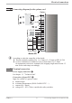
Electrical connections 6 OUT3 transmitter supply 8 2-wire transmitter supply with UT - 1 1 (2) 2 3 + 17,5V 22mA - + 3 4 5 6 5 7 6 8 9 7 10 8 11 9 OUT3 + 12 + 10 13 1 12 15 K 13 (16) 2 - - 11 14 3 13V 22mA 4 14 17 15 2 + 3 - K 1 J x Connection of outputs OUT1 ! and OUT2 " Relay-output KS5_-1_4-_00_ _-_ _ _ and KS5_-1_5-_00_ _-_ _ _ - Relay (250V/2A), potentialfree changeover contact Connection of output OUT3 § Universal output KS5_-1_4-_00_ _-_ _ _und KS5_-1_5-
Electrical connections 0 RS485 interface (with RS232-RS485 interface converter) **** 12 RGND RT = 120...200 Ohm DATA A RGND 11 14 DATA B RT 12 10 13 12 15 DATA B 14 17 DATA A RGND DATA B 13 (16) 14 17 15 DATA A 14 17 15 PC 12 15 13 (16) 11 14 12 15 10 13 11 14 13 (16) 12 10 13 15 R=100 Ohm converter RS485-RS232 max. 1000m ”Twisted Pair” RGND connection optional RT J RT = 120...200 Ohm ****see Interface description Modbus RTU 9499-040-63611 .
Operation 3 Operation 3.1 Front view 1 1 9 0 ! & $ SP.x 2 3 OK 126. 125 è run Ada Err 2 3 5 6 7 8 4 " % § KS 50-1 universal LED colours: LED 1, 2, 3: LED OK: other LEDs: g Front view yellow green red 1 For function states / see LED assignment (Conf/othr/LEd) 2 Lit with limit value 1 ( PArA / Lim ) not exceeded 3 Process value display 4 Set-point, controller output 5 Signals ConF and PArA level 6 Programmer running 7 Self-tuning active 8 Entry in error list 9 Set-point SP.2 or SP.
Operation 3.2 Behaviour after power-on After supply voltage switch-on, the unit starts with the operating level. The unit is in the condition which was active before power-off. If the controller was in manual mode before power-off, the controller starts with the last correcting value after switching on again. 3.3 Operating level The content of the extended operating level is determined by means of BlueControl (engineering tool).
Operation 3.4 Maintenance manager / Error list With one or several errors, the extended operating level always starts with the error list. Signalling an actual entry in the error list (alarm, error) is done by the Err LED in the display. This is applicable only, if at least one limit value function, the loop alarm or the heating current alarm is activated. For display of the error list, press Ù twice.
Operation Name Description LooP Control loop alarm (LOOP) AdA.H Self-tuning heating AdA.C LiM.1 Lim.2 Lim.3 Inf.1 Inf.
Operation 3.5 Self-tuning For determination of optimum process parameters, self-tuning is possible. After starting by the operator, the controller makes an adaptation attempt, whereby the process characteristics are used to calculate the parameters for fast line-out to the set-point without overshoot. The following parameters are optimized when self-tuning: Parameter set 1: Pb1 ti1 td1 t1 Proportional band 1 (heating) in engineering units [e.g.
Operation 3.5.2 Self-tuning start g Self-tuning start can be disabled using BlueControl ® (engineering tool) (Conf/Othr/IAdA). Starting the self-tuning: Self-tuning is started by pressing the Ù and È keys simultaneously, or via the interface. If parameter Conf/Cntr/Strt is set to 1 self-tuning starts also after power-on and when detecting process value oscillations.
Operation 3.5.5 Optimization after start-up or at the set-point The two methods are optimization after start-up and at the set-point. As control parameters are always optimal only for a limited process range, various methods can be selected dependent of requirements. If the process behaviour is very different after start-up and directly at the set-point, parameter sets 1 and 2 can be optimized using different methods. Switch-over between parameter sets dependent of process status is possible (see page ).
Operation Step attempt after start-up Condition: - tunE = 0 and sufficient set-point reserve provided or - tunE = 2 The controller outputs 0% correcting variable or Y.Lo and waits, until the process is at rest (see start-conditions on page 8). Subsequently, a correcting variable step change to 100% or Y.Hi is output. The controller attempts to calculate the optimum control parameters from the process response.
Operation Optimization-at-the-set-point procedure: The controller uses its instantaneous parameters for control to the set-point. In lined out condition, the controller makes a pulse attempt. This pulse reduces the correcting variable by max. 20% 1, to generate a slight process value undershoot. The changing process is analyzed and the parameters thus calculated are recorded in the controller. The optimized parameters are used for line-out to the set-point.
Operation 3.5.7 Optimization at the set-point for 3-point stepping controller As position feedback is not provided, the controller calculates the actuator position internally by adjusting an integrator with the adjusted actuator travel time. For this reason, precise entry of the actuator travel time (tt), as time between stops is highly important. Due to position simulation, the controller knows whether an increased or reduced pulse must be output.
Operation 3.5.8 Examples for self-tuning attempts (controller inverse, heating or heating/cooling) X Start: heating power switched on W Heating power Y is switched off (1). When the change of process value X was constant during one minute (2), 100% the power is switched on (3). Y 0% At the reversal point, the self-tuning Start r attempt is finished and the new parameter are used for controlling to set-point W. X Start: heating power switched off W The controller waits 1,5 minutes (1).
Operation 3.6 Manual tuning The optimization aid should be used with units on which the control parameters shall be set without self-tuning. For this, the response of process variable x after a step change of correcting variable y can be used. Frequently, plotting the complete response curve (0 to 100%) is not possible, because the process must be kept within defined limits.
Operation Formulas K = Vmax * Tu controller behavior PID With 2-point and PD 3-point controllers, the cycle time must be PI P adjusted to t1 / t2 £ 0,25 * Tu 3-point-stepping Pb1 [phy.
Operation 3.8 Alarm handling Max. three alarms can be configured and assigned to the individual outputs. Generally, outputs OuT.1... OuT.6 can be used each for alarm signalling. If more than one signal is linked to one output the signals are OR linked. Each of the 3 limit values Lim.1 … Lim.3 has 2 trigger points H.x (Max) and L.x (Min), which can be switched off individually (parameter = “OFF”). Switching difference HYS.x of each limit value is adjustable. Ü Operaing principle absolut alarm L.
Operation g The variable to be monitored can be selected separately per configuration for each alarm. The following variables are available ( ConF / Lim / Src .x ): Variable (Src x. ) Remark Process value Control deviation Process value - effective set-point. The effective set-point Weff xw is used. E.g with a ramp, this is the changing set-point rather than the target set-point.
Operation 3.9 Operating structure After supply voltage switch-on, the controller starts with the operating levels. The controller status is as before power off. 126 Ù 125 3 sec. 126 PArA Ì Ù PASS 126 ConF Ì Ù 126 CAL Ì PASS Ù PASS 126 Ù End g PArA - level: At PArA - level, the right decimal point of the upper display line is lit continuously. g ConF - level: At ConF - level, the right decimal point of upper display line blinks.
Configuration level 4 Configuration level 4.1 Configuration survey L_r SP.2 SP.E Y.2 mAn C.oFF m.Loc Err.r booS Pid.2 P.run di.Fn quit End Othr Display, operation, interface LOGI Digital inpu ts Out.6 Output 6 OUt.3 Output 3 OUt.2 Output 2 Out.5 Output 5 See output 1 Fnc.2 Src.2 Fnc.3 Src.3 HC.AL LP.AL O.tYP O.Act Y.1 Y.2 Lim.1 Lim.2 Lim.3 LP.AL HC.AL HC.SC P.End FAi.1 FAi.2 OuT.0 Out.1 O.Src See output 1 mAn Corr C.Act FAIL rnG.L rnG.H S.P2C CYCL tunE Strt O.Act Y.1 Y.2 Lim.1 Lim.2 Lim.
Configuration level 4.2 Configurations Cntr Name SP.Fn C.Fnc mAn C.Act FAIL rnG.L rnG.H SP2C KS50/52-1 Value range Description Default 0 Basic configuration of setpoint processing 0 set-point controller can be switched over to external set-point (-> LOGI/ SP.E) 1 program controller 10 controller with start-up circuit 11 Fixpoint / SP.E-/ SP.
Configuration level Name CYCL tunE Strt Adt0 Value range Description Default 0 Characteristic for 2-point- and 3-point-controllers 0 standard 1 water cooling linear 2 water cooling non-linear 3 with constant cycle 0 Auto-tuning at start-up 0 At start-up with step function 1 At start-up with impulse function. Setting for fast controlled systems (e.g.
Configuration level Name fAI1 Value range Description Forcing INP1 (only visible with BlueControl!) 0 No forcing 1 Forcing via serial interface Default 0 InP.2 Name Value range Description Function selection of INP2 0 no function (subsequent input data are skipped) 1 heating current input 2 external set-point (SP.E) 5 default correcting variable Y.E (switchover -> LOGI/ Y.E) S.tYP Sensor type selection 30 0...20mA / 4...20mA Scaling is required. (see chp. 5.3 page 51) 31 0...
Configuration level Name Hour Swit Value range Description OFF..999999 Operating hours (only visible with BlueControl!) OFF..
Configuration level Name O.Act Y.1 Y.2 Lim.1 Lim.2 Lim.3 LP.AL HC.AL HC.SC P.End FAi.1 FAi.2 Out.0 Out.1 O.Src fOut Value range Description Default 5 transmitter supply (only visible without OPTION) 1 Method of operation of output OUT3 (only visible when O.TYP=0) 0 direct / normally open 1 inverse / normally closed 0 Controller output Y1/Y2 (only visible when O.TYP=0) 0 not active 1 active 1 Limit 1/2/3 signal (only visible when O.
Configuration level LOGI Name L_r SP.2 SP.E Y2 yE mAn Configurations Value range Description Local / Remote switching (Remote: adjusting of all values by front keys is blocked) 0 no function (switch-over via interface is possible) 1 active 2 DI1 3 DI2 (only visible with OPTION) 4 DI3 (only visible with OPTION) 5 è - key Switching to second setpoint SP.
Configuration level Name C.oFF m.Loc Err.r booS Pid.2 P.run di.
Configuration level othr Name Value range bAud 0 1 2 3 Addr PrtY 1...247 0 1 2 dELY Unit 0...200 0 1 2 dP 0 1 2 3 LED 0 1 2 C.dEl FrEq 0..200 0 1 MASt 0 Cycl Adr0 AdrU Numb ICof 0 ... 240 -32768 ... 32767 -32768 ... 32767 0 ...
Configuration level Name Value range IAda 0 1 IExo 0 1 ILat 0 1 OFF...9999 Pass IPar 0 1 ICnf 0 1 ICal 0 1 F.Coff 0 1 D2.
Configuration level 4.3 Set-point processing The set-point processing structure is shown in the following picture: SP.x 126 125 run Ada Err Xeff internal set-point Boost Ü ù Programmer external set-point SP.E INP2 SP.Hi 0 1 10 * SP.Lo Start-up circuit Limitation 0/4...20 mA Ö effective r.SP set-point 2.set-point SP.2 - LED Ramp The ramp starts at process value with the following switchings: Index: Ü : int/ext-setpoint switching * : configuration SP.Fn Ö : SP / SP.
Configuration level prevent unreasonably short on and off pulses. The shortest pulses result from ¼ x t1 or ¼ x t2. The characteristic curve is also called “bath tub curve”. T / T1 6,0 relative cycle duration 5,0 4,0 4 x t1 3,0 3 x t1 2,0 2 x t1 1,0 t1 0,0 5 10 15 20 25 30 35 40 45 50 55 60 65 70 75 80 85 90 95 Controller output [%] Parameters to be adjusted: ( PArA/ Cntr) t1 : min. cycle time 1 (heating) [s] t2 : min. cycle time 2 (cooling) [s] 4.4.
Configuration level very weak. Moreover, the correcting variable increases very quickly to max. possible cooling. Parameter F.H2O can be used for changing the characteristic curve. The standard method (see section 4.4.1) is also used for heating. Cooling is also enabled dependent of process temperature . 70 Parameter: t.on = 0.4 sec t.off = 0.2 sec Effective controller output 60 50 40 Water cooling non-linear, F.H2O=1 Water cooling non-linear, F.H2O=2 Water cooling non-linear, F.
Configuration level 4.5 Configuration examples 4.5.1 On-Off controller / Signaller (inverse) InL.1 SP.LO SP SP.Hi InH.1 InP.1Ê 100% Out.1Â HYS.L HYS.H 0% ConF / Cntr: ConF / Out.1: SP.Fn C.Fnc C.Act O.Act Y.1 PArA / Cntr:HYS.L PArA / Cntr:HYS.H PArA / SEtP:SP.LO SP.Hi g = 0 = 0 = 0 =0 =1 = 0...9999 = 0...9999 = -1999...9999 = -1999...9999 set-point /cascade controller signaller with one output inverse output action (e.g. heating applications) output action Out.
Configuration level 4.5.2 2-point and continuous controller (inverse) InL.1 SP.LO InP.1Ê SP SP.Hi InH.1 PB1 100% Out.1Â 0% PB1 20 mA Out.3Â 0/4 mA ConF/Cntr SP.Fn C.Fnc C.Act =0 =1 =0 ConF / Out.1: O.Act Y.1 O.tYP Out.0 Out.1 O.Src Pb1 =0 =1 =1/2 = -1999...9999 = -1999...9999 =1 = 1...9999 ti1 td1 t1 SP.LO SP.Hi = 0,1...9999 = 0,1...9999 = 0,4...9999 = -1999...999 = -1999...9999 ConF / Out.
Configuration level 4.5.3 3-point and continuous controller InL.1 SP.LO InP.1Ê Out.1Â 100% SP PB1 0% Out.2Â Out.3Â 20 mA SP.Hi InH.1 PB2 100% 0% PB1 0/4 mA ConF / Cntr: SP.Fn C.Fnc C.Act ConF / Out.1: O.Act Y.1 Y.2 ConF / Out.2: O.Act Y.1 Y.2 Conf / Out.3: O.typ Out.0 Out.1 O.Src PArA / Cntr: Pb1 Pb2 PArA / SEtP: KS50/52-1 ti1 ti2 td1 td2 t1 t2 SH SP.LO SP.Hi = 0 = 3 = 0 set-point / cascade controller 3-point controller (2xPID) action inverse (e.g. heating applications) = 0 action Out.
Configuration level 4.5.4 3-point stepping controller (relay & relay) InL.1 SP.LO InP.1Ê Out.1Â 100% Out.2Â 0% 100% 0% = 0 = 4 = 0 ConF / Out.1: O.Act Y.1 Y.2 O.Act Y.1 Y.2 Pb1 = = = = = = = ti1 td1 t1 SH tP tt SP.LO SP.Hi = = = = = = = = PArA / SEtP: SP.Hi InH.1 SH SP.Fn C.Fnc C.Act PArA / Cntr: g PB1 ConF / Cntr: ConF / Out.2: SP set-point / cascade controller 3-point stepping controller inverse action (e.g. heating applications) 0 action Out.
Configuration level 4.5.5 D - Y - Off controller / 2-point controller with pre-contact SP.LO InL.1 SP InP.1Ê SP.Hi InH.1 PB1 100% Out.1Â 0% Out.2Â SH ConF / Cntr: SP.Fn C.Fnc C.Act ConF / Out.1: O.Act Y.1 Y.2 O.Act Y.1 Y.2 Pb1 ConF / Out.2: PArA / Cntr: ti1 td1 t1 SH d.SP PArA / SEtP: KS50/52-1 SP.LO SP.Hi d.SP = 0 = 2 = 0 set-point / cascade controller D -Y-Off controller inverse action (e.g. heating applications) = 0 action Out.
Configuration level 4.5.6 KS5_-1 with measured value output phys. quantity Out.1 mA / V phys. quantity Out.0 20mA 10V 0/4mA 0/2V Example: KS5_-1_2-_00_ _-_ _ _ L N 1 2 } 90...250VAC 24VUC 3 4 5 6 7 U OUT3 8 9 10 11 12 13 14 INP1 15 ConF / Out.3: Configuration examples O.tYP + 1 2 3 4 -1999...9999 Out.0 = = = = = Out.1 = -1999...9999 O.Src = 3 46 Out.3 0...20mA continuous Out.3 4...20mA continuous Out.3 0...10V continuous Out.3 2...10V continuous scaling Out.
Parameter setting level 5 Parameter setting level 5.1 Parameter survey InL.1 OuL.1 InH.1 OuH.1 tF.1 Inl.2 OuL.2 InH.2 OuH.2 End Lim Limit value functions b.Lo b.Hi SP.01 Pt.01 SP.02 Pt.02 SP.03 Pt.03 SP.04 Pt.04 SP.05 Pt.05 SP.06 Pt.06 SP.07 Pt.07 SP.08 Pt.08 SP.09 Pt.09 SP.10 Pt.10 InP.2 Input 2 SP.Lo SP.Hi SP.2 r.SP SP.bo t.bo Y.St SP.St t.St InP.1 Input 1 Pb12 Pb22 ti12 ti22 td12 td22 PAr.2 Prog Programmer Pb1 Pb2 ti1 ti2 td1 td2 t1 t2 SH Hys.l Hys.H d.SP tP tt Y2 Y.Lo Y.Hi Y0 Ym.H L.Ym E.
Parameter setting level w w g g g Press the Ù - key to change to the next parameter. After the last parameter of a group, donE is displayed and followed by automatic changing to the next group Return to the beginning of a group, by pressing the Ù key for 3 sec. Unless a key is pressed during 30 seconds, the controller returns to the process value and setpoint display ( Time Out = 30 sec. ) Resetting the configuration parameters to default r chapter 12.1 (page 68) 5.
Parameter setting level PAr.2 Name Pb12 Pb22 Ti22 Ti12 Td12 Td22 Value range Description 1...9999 1 Proportional band 1 (heating) in phys. dimensions ( e.g. °C), 2. parameter set 1...9999 1 Proportional band 2 (cooling) in phys. Dimensions (e.g. °C), 2. parameter set 0...9999 Integral action time 2 (cooling) [s], 2. parameter set 0...9999 Integral action time 1 (heating) [s], 2. parameter set 0...9999 Derivative action time 1 (heating) [s], 2. parameter set 0...
Parameter setting level InP.1 Name InL.1 OuL.1 InH.1 OuH.1 t.F1 Value range Description -1999...9999 Input value for the lower scaling point -1999...9999 Displayed value for the lower scaling point -1999...9999 Input value for the upper scaling point -1999...9999 Displayed value for the lower scaling point -1999...9999 Filter time constant [s] Default Value range Description -1999...9999 Input value for the lower scaling point -1999...9999 Displayed value for the lower scaling point -1999...
Parameter setting level 5.3 Input scaling When using current or voltage signals as input variables for InP.1 or InP.2, scaling of input and display values at parameter setting level is required. Specification of the input value for lower and higher scaling point is in the relevant electrical unit (mA/ V). phys. quantity OuH.x phys. quantity mA / V OuL.x InH.x mA/V InL.x 5.3.1 Input Inp.1 g Parameters InL.1 , OuL.1, InH.1 and OuH.1 are only visible if ConF / InP.1 / Corr = 3 is chosen. S.
Calibration level 6 Calibration level g Measured value correction ( CAL) is visible only if ConF / InP.1 / Corr = 1 or 2 is selected. To access the calibration level, press the key Ù for 3 seconds and then the key Ì to select the CAL-Menu item. Press Ù to confirm. If the password function is activated, a prompt for the PASS is displayed. w w 126 125 Ù 3 Sek 126 Ì PArA 126 Ì ConF 126 CAl Ù ( PASS ) In the calibration menu ( CAL), the measured value can be adapted.
Calibration level Offset correction ( ConF/ InP.1 / Corr =1 ): possible on-line at the process display standard setting offset correction OuL.1new OuL.1old InL.1 X 2-point correction ( ConF/ InP.1 / Corr = 2): SP.X 126 run Ada Err r Ù r PArA 3 sec. Ì r 125 ConF r Ì CAL r Ùr InP.1 r Ù r InL.1 r Ù È È Ì InL1 Ù OuL.1 InP.2 È Ì InH.1 r Ù È InH.1 Ù OuH.1 Ù End È rÙ Ì È rÙ Ì InL.1: The input value of the lower scaling point is displayed.
Calibration level InH.1: The input value of the upper scaling point is displayed. . The operator must adjust the upper input value by means of the process value simulator and confirm the input value by pressing key Ù. OuH.1: The display value of the upper scaling point is displayed. Before calibration OuH.1 is equal to InH.1. The operator can correct the upper display value by pressing keys ÈÌ Subsequently, he confirms the display value by pressing key Ù. 2-point correction ( ConF/ InP.
Programmer 7 Programmer W,X SP.01 SP.02 SP.09 SP.10 W,X W Pt.01 Pt.02 Pt.03 Pt.10 t Programmer set-up: For using the controller as a programmer, select parameter Cntr /SP.Fn = 1 in the ConF menu. The programmer is started via one of digital inputs di1..3 or the è key. Which input shall be used for starting the programmer is determined by selecting parameter LOGI/P.run = 2 / 3 / 4 / 5 in the ConF menu accordingly.
Special functions 8 Special functions 8.1 Start-up circuit 3 4 5 6 7 W Set-point 1 Process value 2 SP.St SP.St-1K SP.St-40K tt.Str Power on Disturbance tt.Str t The start-up circuit is a special function for temperature control, e.g. hot runner control. High-performance heating cartridges with magnesium oxyde insulation material must be heated slowly to remove moisture and prevent destruction. Operating principle: 1 After switching on the supply voltage, line-out to the start-up set-point SP.
Special functions 8.2 Boost function W + SP.bo SP.bo Set-point Process value W t The boost function causes short-time increase of the set-point, e.g. for removing "frozen" material rests from clogged die nozzles with hot-runner control. If configured (® ConF/ LOGI/ booS), the boost function can be started via digital input di1/2/3, with the function key on the instrument front panel or via the interface (OPTION). The set-point increase around boost set-point PArA /SEtP/SP.
Special functions 8.3 KS50/52-1 as Modbus master a This function is only selectable with BlueControl (engineering tool)! Additions othr Name MASt Cycl AdrO AdrU Numb (only visible with BlueControl!) Value range Description Default 0 Controller is used as Modbus master 0 Slave 1 Master 0...200 Cycle time [ms] for the Modbus master to transmit its data to the 60 bus. 1...65535 Target address to which the with AdrU specified data is given out on 1 the bus. 1...
Special functions 8.4 Linearization Linearization for input INP1 Access to table “ Lin” is always with selection of sensor type S.TYP = 18: special thermocouple in INP1, or with selection of linearization S.Lin 1: special linearization. Dependent of input type, the input signals are specified in µV or in Ohm dependent of input type. With up to 16 segment points, non-linear signals can be simulated or linearized. Every segment point comprises an input (In.1 … In.16) and an output (Ou.1 … Ou.16).
BlueControl 9 BlueControl BlueControl® is the projecting environment for the PMA BluePortâ controller series. The following 3 licences with graded functionality are available: The "Universal BlueControl©" Software comprises all functions of the Expert-version. All BluePort devices can be triggered via this software. The mini version is - free of charge - at your disposal as download at PMA homepage www.pma-online.de or on the PMA-CD (please ask for).
Versions 10 Versions KS 5 KS 50-1 Format 48 x 96 KS 52-1 Format 96 x 96 1 0 0 0 2 Flat pin connector Screw terminals 0 1 90..250V AC,INP2, 3 relays 24VAC / 18..30VDC, INP2, 3 relays 90..250V AC, INP2, 2 relays+ mA/V/logic 24VAC / 18..30VDC, INP2, 2 relays+ mA/V/logic 0 1 2 3 90..
Versions Accessory equipment with ordering information Description Heating current transformer 50A AC PC-adaptor for the front-panel interface (RS232) Standard rail adapter Operating manual Operating manual Operating manual Operating manual Interface description Modbus RTU Interface description Modbus RTU BlueControl (engineering tool) BlueControl (engineering tool) BlueControl (engineering tool) BlueControl (engineering tool) 62 German English French Russian German English Mini Basic Expert Universal Do
Technical data 11 Technical data CONTROL INPUT DI1 Configurable as switch or push-button (the adjustment is possible only in common for all digital inputs)! Connection of a potential-free contact suitable for switching “dry” circuits. INPUTS PROCESS VALUE INPUT INP1 Resolution: Decimal point: Dig. input filter: Scanning cycle: Measured value correction: > 14 bits 0 to 3 digits behind the decimal point adjustable 0,000...
Technical data OUTPUTS OUT5, OUT6 (OPTION) OUTPUTS Galvanically isolated opto-coupler outputs. Grounded load: common positive voltage. Output rating: 18...32 VDC; ≤ 70 mA Internal voltage drop: ≤ 1V with Imax. Protective circuit: built-in against short circuit, overload, reversed polarity (free-wheel diode for relay loads).
Technical data Altitude To 2000 m above sea level Certifications Shock and vibration Type tested to EN 14597 (replaces DIN 3440) Vibration test Fc (DIN 68-2-6) Frequency: Unit in operation: Unit not in operation: With certified sensors applicable for: 10...
Safety hints 12 Safety hints a This unit was built and tested in compliance with VDE 0411-1 / EN 61010-1 and was delivered in safe condition. The unit complies with European guideline 2004/108/EG (EMC) and is provided with CE marking. The unit was tested before delivery and has passed the tests required by the test schedule. To maintain this condition and to ensure safe operation, the user must follow the hints and warnings given in this operating manual.
Safety hints a MAINTENANCE, REPAIR AND MODIFICATION The units do not need particular maintenance. Warning When opening the units, or when removing covers or components, live parts and terminals may be exposed. Before starting this work, the unit must be disconnected completely. After completing this work, re-shut the unit and re-fit all covers and components. Check if specifications on the type label must be changed and correct them, if necessary.
Safety hints 12.1 Reset to default 1 2 3 ÌÈ + Power on È Ù SP.x FAC torY 1. run SP.x Ada Err FAC no run Ada Err SP.x FAC YES run Ada Err SP.x 4 FAC COPY run Ada Err 8.8.8.8. SP.x 8.8.8.8. run Ada Err 2. In the event of faulty configuration, the instrument can be reset to default. In the event of faulty configuration, the instrument can be reset to default.
Index D Digital inputs di1, di2, di3 Configuration . . . . . . . . . . 34 Technical data . . . . . . . . . . 64 0-9 2-point correction. . . . . . . . . . . . 55 A Accessories . . . . . . . . . . . . . . . 62 Alarm handling . . . . . . . . . . 25 - 26 E Environmental conditions Equipment . . . . . . . . Error list . . . . . . . . . Error status . . . . . . . . B BlueControl. . . . . . . . . . . . . . . 61 Boost function . . . . . . . . . . . . . 58 Bus interface Technical Data. . . . . . . . . . 65 . . .
O Offset correction . . . . . . Optimization at the setpoint Output OUT1 Configuration . . . . Technical data . . . . Output OUT2 Configuration . . . . Technical data . . . . Output OUT3 Configuration . . . . Technical data . . . . Output OUT5 Configuration . . . . Technical data . . . . Output OUT6 Configuration . . . . Technical data . . . . Set-point processing . . . . . . . . . . 38 Start-up circuit . . . . . . . . . . . . . 57 . . . . . . 54 . . . . . . 19 T Thermocouple measuring range . . . .
KS50/52-1 71
Subject to alterations without notice Änderungen vorbehalten Sous réserve de toutes modifications © PMA Prozeß- und Maschinen-Automation GmbH P.O.B.