
Manual
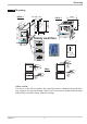
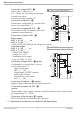

Connection of outputs OUT1 ! and OUT2 "
Relay-output KS5_-1_4-_00_ _-_ _ _ and KS5_-1_5-_00_ _-_ _ _
- Relay (250V/2A), potentialfree changeover contact
Connection of output OUT3 §
Universal output KS5_-1_4-_00_ _-_ _ _und KS5_-1_5-_00_ _-___
Note: Mind the safety switch.
- current (0/4...20mA)
- voltage(0/2...10V)
- Transmitter power supply
- Logic (0..20mA / 0..12V)
a
The analog outputs OUT3 and transmitter supply voltage U
T
are connected to
different voltage potentials. For this reason, an external galvanic connection of
OUT3 and U
T
is not permissible for analog outputs.
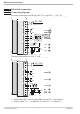
Electrical connections
KS50/52-1 10 Terminal connection
1
2
3
K
+
-
+
-
13V
22mA
6 OUT3 transmitter supply
1
3
4
5
6
7
8
9
10
11
12
13
14
15
17
(2)
(16)
1
2
3
4
7
5
8
6
9
10
11
12
13
14
15
1
2
3
K
+
-
+
-
+
-
17,5V
22mA
OUT3
J
x
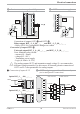
8 2-wire transmitter supply with U
T
Option KS5_-1_ _-100 _ _-_ _ _
1
2
3
4
5
+24VDC
5mA
5mA
0V
Option KS5_-1_ _-800 _ _-_ _ _
1
2
3
4
5
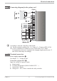
7 Connection of inputs di 2/3
7
8
9
7
8
9
3
4
7
5
8
6
9
10
+
_
SSR
+
_
SSR
+
_
SSR
Series connection
Parallel connection
+
_
SSR
7
8
9
Logic
4V
4V
4V
12V
I =22mA
max
I =22mA
max
12V
6 OUT3 as logic output with solid-state relay
(series and parallel connection)