
Manual

2 Electrical connections
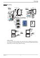
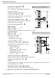
2.1 Connecting diagram
Electrical connections for all types KS 5x-1 exept KS 5_-1_4-_ 00_ _-_ _
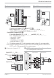
Electrical connections for KS 5_-1_4-_____-__
* Safety switch 10Vi mA/Pt (input INP1 current”10V” i mA/Pt/mV)
** Safety switch U i I (output OUT3 current”U” i voltage”I”)
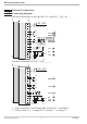
Electrical connections
Connecting diagram 7 KS50/52-1
L
N
90...250V
24V AC/DC
mA
mA
0..10 V
HC
di1
INP1
INP2
OUT3
OUT2
OUT1
1
2
3
4
7
5
8
6
9
10
11
12
13
14
15
ab c d
U
Logic
KS 5_-1. -.....-...
KS 5_-1. -.....-...
2
3
C
N/O
N/O
C
N/O
N/C
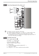
L
N
90...250V
24V AC/DC
mA
0..10 V
di1
INP1
OUT3
OUT2
OUT1
1
2
3
4
7
5
8
6
9
10
11
12
13
14
15
ab c d
U
Logic
C
N/O
N/C
N/O
C
N/C