
Manual
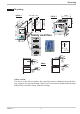
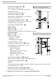

2.2 Connecting diagram for the options card
g
According to order the controller is fitted with:
w
flat-pin terminals combined for 1 x 6,3mm or 2 x 2,8mm to DIN 46 244
w
or screw terminals for conductor cross section from 0,5 to 2,5mm²
On instruments with screw terminals, the stripping length must be min. 12
mm. Select end crimps accordingly.
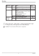
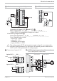
2.3 Terminal connection
Power supply connection 1
See chapter 11 "Technical data"
Connection of input INP1 2
Input for variable x1 (process value)
a thermocouple
b resistance thermometer (Pt100/ Pt1000/ KTY/ ...)
c current (0/4...20mA)
d voltage (0/2...10V) *Note: consider the safety switches.
Electrical connections
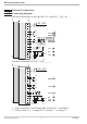
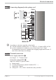
KS50/52-1 8 Connecting diagram for the options card
di2
di3
U
T
Option
RXD-B
GND
RXD-A
TXD-B
TXD-A
RS485 RS422
Modbus RTU
RGND
DATA B
DATA A
+24V DC
24V GND
1
2
3
4
7
5
8
6
9
10
11
12
13
14
15
1
3
4
5
6
7
8
9
10
11
12
13
14
15
17
(2)
(16)
OUT5
OUT6
24 VDC
24 VDC
KS5_-1..- ....-...8