VHF 480 Owner’s Manual Guide d’utilisation CLASS 'D' DSC MARINE RADIO RADIO MARITIME ASN DE CLASSE “D” MODEL / MODÈLE 15088198
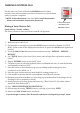
Making a Distress Call Lift the red cover. Press and hold the DISTRESS button for three seconds. Your radio transmits your boat’s location every few minutes until you receive a response. ##NOTE: If the radio displays Enter User MMSI, cancel the automatic distress call and make a normal voice distress call. Making a Voice Distress Call Speak slowly - clearly - calmly. For future reference, write your boat’s name & call sign here: Lift the red cover and press the DISTRESS button. 1.
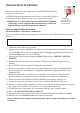
Faire un appel de détresse Soulevez le couvercle rouge. Maintenez la touche DISTRESS enfoncée pendant trois secondes. Le VHF480 transmet la position de votre bateau à intervalles réguliers de quelques minutes, jusqu’à ce que vous receviez une réponse. ##REMARQUE : Si la radio affiche Enter User MMSI (Entrer l’ISMM de l’utilisateur), annulez l’appel de détresse automatique et faites un appel de détresse couvercle rouge etvocal standard. Soulevez le couvercle rouge et appuyez sur la touche DISTRESS.
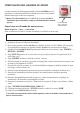
Cómo hacer una llamada de apuro Levante la tapa roja. Mantenga oprimido el botón DISTRESS por tres segundos. La radio transmitirá la localidad de su nave cada cuantos minutos hasta que reciba una respuesta. ##Nota: Si la radio exhibe (Inserte el MMSI del usuario), cancele la llamada de apuro automática y haga una llamada de apuro normal por voz. Cómo hacer una llamada de apuro por voz Levante la tapa roja y oprima el botón DISTRESS. Hable despacio -- claro -- y con calma.
Contents Making a Voice Distress Call........................................... 2 Faire un appel de détresse vocal . ..................................... 3 Cómo hacer una llamada de apuro por voz ................. 4 Introduction ..............................1 Features ..................................... 1 Manual overview .................... 1 Getting Started ..........................2 What’s included ....................... 2 Parts of the Radio . ................. 3 Parts of the Microphone........
Connecting the radio............ 28 Connecting the accessory cable...................................... 29 Connecting to a GPS receiver ................................ 29 Connecting to a Chartplotter for Data Output................................... 30 Connecting to an External Speaker.................................. 31 Maintenance and Troubleshooting....................31 Engine Noise Suppression...... 33 Specifications............................33 Radio Specifications ..............
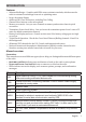
Introduction Features xx Submersible Design - Complies with IPX4 water-resistant standards, which means the xx xx xx xx xx xx xx xx xx radio is resistant from damage from rain or splashing water. Large, dot matrix display Advanced DSC Class D functions, including Test Calling Channel Select buttons on the microphone. Memory scan mode - Lets you save channels to memory and monitor them in quick succession.
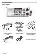
Getting Started What’s included Mounting Bracket and Knobs Mounting Hardware Microphone Hanger and Mounting Hardware Not shown: Spare Fuse DC Power Cord 2 English Accessory Cable
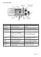
Parts of the Radio LCD display ENT- 1W/25W button CHANNEL UP / CHANNEL DOWN buttons VOLUME-PWR (power) knob (turn clockwise to increase volume) Microphone cord CALLMENU button 16/9-TRI (triple/dualwatch) button DISTRESS button with CLR-SCAN cover (channel scan) button WX-MEM button SQUELCH knob (turn clockwise to decrease channel noise) Button Press to... Press and hold to... ENT-1W/25W Select an option on a menu or display the GPS data. Change the transmit power (see page 12).
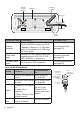
Antenna connector (SO238) Accessory cable Heat sink Red wire (+) 13.8V DC ANTENNA Black wire (-) Power Cable Connector/Cable Connects to... For details, see ... Antenna connector External VHF antenna with a male PL259 (SO238) connector and 50 Ω impedance. Minimum 3 ft, 3dB rated antenna for sailboats, 8 ft, 6 dB rated for power boats. Connecting the radio (see page 28). Power cable pigtail Nominal 13.8 VDC power supply with negative ground (10.5 VDC to 16.0 VDC) (Red wire +, black wire -).
Turning on the Radio Turn the VOLUME-PWR knob clockwise to turn on the radio. As it powers on, the radio displays the user MMSI number; if there is no MMSI set, the radio displays MMSI not entered. When it powers on, the radio selects the last channel used. Setting the UIC Channel Mode (USA/CAN/INT) The radio comes preset to use the UIC channels assigned for the United States. If you are operating in an area that uses Canadian or international UIC channels, you will need to change the channel mode.
Watch Mode What It Does Use It When To Turn it on./off... Weather Alert Checks for alerts on the last weather channel you used every seven seconds. You want to be made aware of severe weather conditions in your area. conditions in your area. Select WX Alert Mode in Setup submenu, and then choose ON or OFF. Triple Checks for activity on channels 16 and 9 every two seconds. You want to monitor a channel yet maintain a watch on channels 16 and 9. Press and hold 16/9-TRI for two seconds.
Using the radio in normal mode xx To transmit, press and hold PUSH TO TALK on the microphone. Release the button when you are finished talking. xx For the best sound quality, hold the microphone about two inches from your mouth while you’re talking. xx Press CHANNEL UP on the radio or the microphone to move up one channel at a time. Press and hold either button to scroll quickly up the channels. xx Press CHANNEL DOWN on the radio or the microphone to move down one channel at a time.
Normal mode with both Weather Alert and Triple/Dual Watch You can activate Weather Alert Watch and Monitoring Channel 25 Triple/ Dual Watch at the same time. The radio performs both checks at their 09 16 09 16 09 scheduled time. 16 Triple Watch: Every 2 seconds, wx the radio checks channels 9 & 16. Scan mode WX Alert : Every 7 seconds, the radio checks the most You can save channels into memory and recently-used weather channel. then use scan mode to monitor those channels.
Scan mode with Weather Alert Watch If you activate Weather Alert Watch while operating in scan mode, the radio checks the most recently-used weather channel every seven seconds, then continues scanning the next channel in memory. To turn Weather Alert Watch on or off, press and hold CALL-MENU while the radio is idle. Select Setup and then WX Alert Mode. Use CHANNEL UP and CHANNEL DOWN to choose WX Alert Mode setting ON or Off.
Using the radio in weather mode xx You cannot transmit while in weather mode. xx To enter weather mode, press WX-MEM. xx Weather mode can filter out alerts that do not affect your location if the location code (FIPS code) of the alert is entered in your radio (see page 13). If you have no FIPS codes programmed into your radio, the radio will notify you of all alerts in any area. xx To turn off the radio’s alert tone, press any button.
Using Your Radio To display the radio call menu, press CALL-MENU. To display the radio normal menu, press and hold CALL-MENU. The menu has the following options: Press and hold - Setup System USA/CAN/INT Dual/TriWatch GPS Setup FIPS Codes Auto CH SW POS Reply Test Reply Group MMSI User MMSI WX Alert Mode [Exit] Contrast Lamp Adjust Key Beep [Exit] [Exit] (Close Menu) Using the Menu xx An arrow on the left side indicates the current selection.
Setting the squelch level The squelch feature reduces the level of static on the speaker by filtering out the background channel noise. At the lowest squelch level, the speaker plays all radio signals, including any noise on the channel. Setting the squelch level higher filters out channel noise and lets only actual radio transmissions through.
##NOTE: By default, when you change to channel 16, the radio automatically boosts the power to 25 Watts. Be sure to change the power back to 1 Watt if you are not making an emergency transmission. Some channels (for example, channels 13 and 67) limit the power of transmission to 1 Watt so that there is less interference between boaters attempting to use the channel at the same time. If you switch to one of these channels, the radio changes back to 1 Watt automatically.
Follow the steps below to edit the list of FIPS codes. You can store up to 30 different FIPS codes in your radio. Press and hold - Setup Use the up and down arrows to adjust each of the six digits in turn. FIPS Codes FIPS Code 000000 16 [New] Back[CLR] Forward[ENT] Display the normal menu and choose the Setup sub-menu. 1. Select FIPS Codes. The screen displays any previously-entered FIPS codes. 2. To add a new FIPS code, select New. 3.
the radio is in. For example, if you turn on your radio and it is connected to a GPS unit but the GPS is not sending valid data, the radio displays Check GPS. At the 30 minute mark with no GPS data input from the GPS unit, the radio display changes to Input Position.
1. Display the normal menu and choose the Setup sub-menu. 2. Select GPS Setup and then choose Position Set. 3. The GPS manual input screen displays; the fields to be entered blink. The cursor highlights the hour. Use CHANNEL UP and CHANNEL DOWN to set the displayed hours to match coordinated universal time (UTC, also call Greenwich Mean Time and Zulu Time). When the display matches UTC time, press ENT-1W/25W.
Feature Menu Item Function Test Call Test Make sure your radio is working and configured correctly. Name and MMSI Directory Directory Store a list of 20 names and MMSI identification codes for DSC calls. Standby Mode Standby Automatically respond to all DSC calls within an “Unavailable” status. Received Call Log Receive Log Display the last 10 distress calls received by the radio and the last 20 general calls.
4. When the first digit is correct, press ENT-1W/25W. The cursor moves to the next digit. Enter the remaining eight digits of the MMSI number in the same way. If you make a mistake while entering a number, press CLR-SCAN to erase the wrong number and the cursor is moved to the left digit. 5. When the ninth digit is correct, press ENT-1W/25W. The radio displays the new MMSI number and asks you to confirm. To save this MMSI number, select Yes; the radio asks for confirmation again.
Follow the steps below to edit the MMSI numbers in your directory: Press CALL-MENU to display the call menu. Select Directory. The screen displays any previously-entered MMSI numbers and names. To add a new MMSI number to the directory, select New. The radio prompts you to enter the nine-digit MMSI number. Use CHANNEL UP and CHANNEL DOWN to change the first digit; the CHANNEL UP button increases the number and the CHANNEL DOWN button decreases it. 5. When the first digit is correct, press ENT-1W/25W.
Call type What it does When to use it Individual Calls a single station using the User MMSI. Any time you want to talk to another station. Group Calls all the stations that have the Any time you want with the whole same Group MMSI as yours. group you are traveling with at the same time. All Ships Calls all stations within range of your radio. Safety warnings (e.g., debris in the water) or any urgent situation. Suppose you are coordinating safety for a sailboat race.
5. The radio displays the MMSI number you are about to call and asks you to confirm. If you want to call the displayed MMSI number, select Send. To cancel the call, select Cancel. 6. The radio automatically switches to channel 70 to transmit the call request. xx When the other station accepts the call, both radios switch to the selected response channel for voice transmission. xx If the other station cannot respond on the channel you selected, the radio displays Not support CH.
2. The radio displays the list of distress conditions; use CHANNEL UP and CHANNEL DOWN to choose the nature of your distress, then press and hold DISTRESS for three seconds. Undesignated Sinking Fire Adrift Flooding Abandoning Collision Piracy.Armed Grounding Overboard Capsizing 3. If no MMSI number has been programmed, the radio prompts you to enter your MMSI number. Canceling an automatic distress call While the radio is waiting for a response, it gives you the option of canceling the call.
DSC Call Type Receive Log Information Distress MMSI (or name), position, time, nature code. Distress Acknowledge MMSI (or name), distress MMSI, position, time, nature code. Distress Relay MMSI (or name), distress MMSI, position, time, nature code. Distress Relay Acknowledge MMSI (or name), distress MMSI, position, time, nature code. Geographical MMSI (or name), category code, communication channel number. All Ships MMSI (or name), category code, communication channel number.
Press Test Test [Manual] JIM CASSIDY KENT NEWMAN Back[CLR] 16 Select[ENT] If you want to send a test call to a station that is not in your directory, select Manual. The radio prompts you to enter the MMSI number you want to call. Enter the MMSI number the same way you enter directory entries (see page 17). Enter all nine digits and press ENT1W/25W button. 4. The radio displays the MMSI number you are about to call Test and asks you to confirm.
Press and hold - Test Reply Auto Manual Setup Test Reply Back[CLR] 16 Select[ENT] 4. To disable automatic test call reply, repeat the steps above and select Manual. Position Request and Reply Requesting another station’s position (POS Request) Anytime you need to know where another boat currently is—to find your boating partners, to respond to a request for assistance, etc.—you can send a position request to their radio: 1. Press CALL-MENU to display the call menu. 2.
position reply for safety reasons or because they subscribe to a marine towing service. Sometimes—for example, in some competitive situations—you may not want other stations to get your position without your manual confirmation 1. Press and hold CALL-MENU to display the normal menu. 2. Select Setup and then POS Reply. 3. Choose Auto and press ENT-1W/25W. The radio will automatically transmit your position when it receives a position request. 4.
channel switching. If you receive an individual call, the radio will respond with an unattended code, just as if the radio were in Standby. 1. Press and hold CALL-MENU to display the normal menu. 2. Select Setup and then Auto CH SW. 3. Choose Off and press ENT-1W/25W. The radio will not automatically switch channels until you reactivate this feature. ##NOTE: Use this feature with caution. Deactivating automatic switching and then forgetting it can make it hard for you to receive DSC calls.
5. Remove the bracket from the radio, and use the mounting hardware to secure the bracket to the mounting surface. 6. Install the radio back into the mounting bracket.
Connecting the accessory cable Use the accessory cable to connect the radio to a GPS receiver, a GPS chartplotter, and an external speaker. The wiring diagram below shows the connections for each accessory. Accessory cable wires Connects to...
See page 20 to manually set the GPS coordinates. Configuring the GPS If the radio is receiving valid GPS data, it will automatically set the clock to your local time based on the GPS location. You can adjust your local time forward or back one hour if necessary (for example, if you are close to the border of a time zone); you can also adjust for Daylight Savings Time. Follow the steps below to adjust the time: Press and hold - Setup Use the up and down arrows to adjust the time by one hour.
Connecting to an External Speaker You can use an external speaker to monitor the radio from a different part of your boat or in a noisy environment. If you adjust the VOLUME-PWR knob on the radio, it will also adjust the external speaker volume. Your radio supports an external speaker with the following specifications: xx Minimum impedance of 4 Ohms xx Minimum power handling of 10 Watts 1. Connect the BLACK wire of the accessory cable to the GROUND WIRE of your external speaker. 2.
Problem Things to Try I can transmit, but no one can hear me. Check your UIC channel settings (see Setting the UIC channel mode (USA/CAN/INT) on page 5). The display flashes, and I don’t know why. The display will flash if the radio is in a watch mode or in scan mode. Try turning off scanning, Weather Alert Watch, or Triple/Dual Watch (see page 5). I can’t read the display. Adjust the contrast and backlight brightness level (see page 14). The display is too bright at night.
Engine Noise Suppression Interference from the noise generated by the electrical systems of engines is sometimes a problem with radios. Your radio has been designed to be essentially impervious to ignition noise and alternator noise. However, in some installations it may be necessary to take measures to further reduce the effect of noise interference.
General Power Output 1 watt or 25 watt (user selectable) Power Requirement 25 watts output: 6A@13.
Channel name/description Used for: NON-COMMERCIAL (recreational or voluntary ships only) messages about the needs of the ship, including fishing reports, rendezvous, scheduling repairs and berthing information COMMERCIAL (working ships only) messages about the needs of the ship or the business the ship is engaged in PUBLIC CORRESPONDENCE/ MARINE OPERATOR calls to the marine operator at a public coast station. Marine operators can connect you to the telephone network so you can make and receive calls.
Ch No. 17 18A 19A 20 20A RX Freq 156.8500 156.9000 156.9500 161.6000 157.0000 TX Freq 156.8500 156.9000 156.9500 157.0000 157.0000 Status Simplex, 1W Simplex Simplex Duplex Simplex Name on display Govt maritime control Commercial Commercial Port operation Port operation 21A 22A 23A 24 25 26 27 28 63A 65A 66A 67 68 69 70 71 72 73 74 75 76 77 78A 79A 80A 81A 82A 83A 84 85 86 87** 88** 157.0500 157.1000 157.1500 161.8000 161.8500 161.9000 161.9500 162.0000 156.1750 156.2750 156.3250 156.3750 156.
*A indicates simplex use of the ship station transmit side of an international duplex channel, and that operations are different from that of international operations on that channel. **Channels 87 & 88 revert from duplex to simplex operation. AIS channels are not supported. Canadian Marine Channels and Frequencies Ch No. 1 2 3 4A 5A 6 7A 8 9 10 11 12 13 14 15 16 17 18A 19A 20 21A 22A 23 24 25 26 27 28 60 61A 62A 63A 64 64A RX Freq 160.6500 160.7000 160.7500 156.2000 156.2500 156.3000 156.3500 156.
Ch No. 65A 66A 67 68 69 70 71 72 73 74 75 76 77 78A 79A 80A 81A 82A 83 83A 84 85 86 87 88 RX Freq 156.2750 156.3250 156.3750 156.4250 156.4750 (156.5250 156.5750 156.6250 156.6750 156.7250 156.7750 156.8250 156.8750 156.9250 156.9750 157.0250 157.0750 157.1250 161.7750 157.1750 161.8250 161.8750 161.9250 157.3750 157.4250 TX Freq 156.2750 156.3250 156.3750 156.4250 156.4750 156.5250) 156.5750 156.6250 156.6750 156.7250 156.7750 156.8250 156.8750 156.9250 156.9750 157.0250 157.0750 157.1250 157.1750 157.
Ch No. 10 11 12 13 14 15 16 17 18 19 20 21 22 23 24 25 26 27 28 60 61 62 63 64 65 66 67 68 69 70 71 72 73 74 75 76 77 78 RX Freq 156.5000 156.5500 156.6000 156.6500 156.7000 156.7500 156.8000 156.8500 161.5000 161.5500 161.6000 161.6500 161.7000 161.7500 161.8000 161.8500 161.9000 161.9500 162.0000 160.6250 160.6750 160.7250 160.7750 160.8250 160.8750 160.9250 156.3750 156.4250 156.4750 (156.5250) 156.5750 156.6250 156.6750 156.7250 156.7750 156.8250 156.8750 161.5250 TX Freq 156.5000 156.5500 156.
Ch No. 79 80 81 82 83 84 85 86 87* 88* RX Freq 161.5750 161.6250 161.6750 161.7250 161.7750 161.8250 161.8750 161.9250 157.3750 157.4250 TX Freq 156.9750 157.0250 157.0750 157.1250 157.1750 157.2250 157.2750 157.3250 157.3750 157.
Event Blizzard Warning SAME Code BZW Type Warning Coastal Flood Watch Coastal Flood Warning Dust Storm Warning Flash Flood Watch Flash Flood Warning Flash Flood Statement Flood Watch Flood Warning Flood Statement Freeze Warning High Wind Watch High Wind Warning Hurricane Watch Hurricane Warning Hurricane Statement Severe Thunderstorm Watch Severe Thunderstorm Warning Severe Weather Statement Special Marine Warning Special Weather Statement Tornado Watch Tornado Warning Tropical Storm Watch Tropical Storm
Event Hazardous Material Warning Law Enforcement Warning Local Area Emergency 911 Telephone Outage Emergency Nuclear Power Plant Warning Radiological Hazard Warning Shelter In-Place Warning Volcano Warning Administrative Message Practice/Demo Required Monthly Test Required Weekly Test Biological Hazard Warning Boil Water Warning Chemical Hazard Warning Dam Watch Dam Break Warning Contagious Disease Warning Emergency Action Notification Emergency Action Termination Evacuation Watch Food Contamination Warning
No Response Event Code TXB Transmitter Backup On TXF Transmitter Carrier On TXO Transmitter Carrier On TXP Transmitter Primary On NMEA Operation This radio supports NMEA0183 version 4.10. NMEA Input If you have difficulty getting your radio to receive data from your GPS receiver, check the device’s configuration. It should be set to the following parameters: Baud rate 4800 bps Data bits 8 Parity None Stop bits 1 Data amplitude Over 2.
Regulations and Safety Warnings Maritime radio services operation Warning! This transmitter will operate on channels/frequencies that have restricted use in the United States. The channel assignments include frequencies assigned for exclusive use of the U.S. Coast Guard, use in Canada, and use in international waters. Operation on these frequencies without proper authorization is strictly forbidden. See the channel tables beginning on page 35 for a list of available channels and their uses.
• Small whip antennas (3 dB) or smaller should be installed keeping at least a two foot separation distance between the radiating element and people. • Medium antennas (6 dB) should be installed keeping at least a three foot separation distance. • Larger antennas (9 dB) should be installed keeping at least a four foot separation distance. • No person should touch the antenna or come into the separation distance when the radio is transmitting.
WARRANTY PERIOD HAS EXPIRED. SOME STATES DO NOT ALLOW LIMITATIONS ON HOW LONG AN IMPLIED WARRANTY LASTS, SO THE ABOVE LIMITATIONS MAY NOT APPLY TO YOU. WE DO NOT ACCEPT LIABILITY BEYOND THE REMEDIES PROVIDED FOR IN THIS LIMITED WARRANTY OR FOR CONSEQUENTIAL OR INCIDENTAL DAMAGES, INCLUDING, WITHOUT LIMITATION, ANY LIABILITY FOR THIRD-PARTY CLAIMS AGAINST YOU FOR DAMAGES, FOR PRODUCTS NOT BEING AVAILABLE FOR USE, OR FOR LOST DATA OR LOST SOFTWARE.
Maintenance is the Owner’s Responsibility Cleaning, polishing, lubricating, replacing filters, tuning, replacing worn parts, using your purchased product according to the user’s manual, and regularly maintaining your purchased product is your responsibility. What if I purchased a Plus Protection Plan? Service will be provided to you under the terms of the Plus Protection Plan Contract. Please refer to that contract for details on how to obtain service. How State Law Relates to the Warranty.
QUESTIONS? Contact your local West Marine store. Call 1-800-BOATING Visit our website at www.westmarine.com QUESTIONS? Contactez votre magasin West Marine local. Appelez 1-800-BOATING Contactez-nous au www.westmarine.