ULTRALINE (MODELS 7400/7401) VERSALINK (MODELS 328W10/328W11) USER GUIDE Copyright © 2005 Westell, Inc. 030-300432 Rev.
Westell Router (Models 7400, 7401, 328W10, 328W11) User Guide TABLE OF CONTENTS 1. PRODUCT DESCRIPTION ..................................................................................................................................4 2. SAFETY INSTRUCTIONS ...................................................................................................................................4 3. REGULATORY INFORMATION ........................................................................................
Westell Router (Models 7400, 7401, 328W10, 328W11) User Guide 13. CONFIGURATION .............................................................................................................................................57 13.1 Single Static IP – Single IP Address PassThrough ..................................................................................57 13.2 Service Configuration .....................................................................................................................
Westell Router (Models 7400, 7401, 328W10, 328W11) User Guide 1. PRODUCT DESCRIPTION Your Westell® Router provides reliable, high-speed, Internet access to your existing small office phone line. Your ADSL connection is “always-on” ending the hassles of dial-up modems and busy signals. Installation is easy ... no tools ... no headaches. Simply connect the hardware, apply power, and perform the simple software configuration for Router and you are on the Internet.
Westell Router (Models 7400, 7401, 328W10, 328W11) User Guide 3. REGULATORY INFORMATION 3.1 FCC Compliance Note (FCC ID: CH8-A90328XX-07) This equipment has been tested and found to comply with the limits for a Class B digital device, pursuant to Part 15 of the Federal Communication Commission (FCC) Rules. These limits are designed to provide reasonable protection against harmful interference in a residential installation.
Westell Router (Models 7400, 7401, 328W10, 328W11) User Guide A plug and jack used to connect this equipment to the premises wiring and telephone network must comply with the applicable FCC Part 68 rules and requirements adopted by the ACTA. A compliant telephone cord and modular plug is provided with this product. It is designed to be connected to a compatible modular jack that is also compliant. See installation instruction for details.
Westell Router (Models 7400, 7401, 328W10, 328W11) User Guide to certified equipment should be coordinated by a representative, and designated by the supplier. Refer to section 19 in this User Guide for further details. The termination on an interface may consist of any combination of devices subject only to the requirement that the sum of the Ringer Equivalence Numbers of all the devices does not exceed five.
Westell Router (Models 7400, 7401, 328W10, 328W11) User Guide 4. NETWORKING REQUIREMENTS The following system specifications are required for optimum performance of the Router via 10/100 Base-T Ethernet, Wireless, or USB installations. CONNECTION TYPE MINIMUM SYSTEM REQUIREMENTS • • ETHERNET (All Models) WIRELESS IEEE 802.11g (Models 328W10, 328W11) USB (Models 7400, 328W10) • • • • • • • • • • • • • • • • • • • 030-300432 Rev.
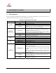
User Guide 5. HARDWARE FEATURES 5.1 LED Indicators This section explains the LED States and Descriptions of your Router. LED indicators are used to verify the unit’s operation and status. Please refer to the table of the Model you are using. LED States and Descriptions (Model 7400) LED Description Modem power is ON. Modem power is OFF. POWER POST (Power On Self Test), Failure (not bootable) or Device Malfunction.
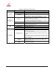
User Guide LED States and Descriptions (Model 7401) LED Description Modem power is ON. Modem power is OFF. POWER POST (Power On Self Test), Failure (not bootable) or Device Malfunction. Note: The Power LED should be red no longer than Solid Red two seconds after the power on self test passes. Powered device is connected to the associated port (includes devices with wake-on LAN capability where slight voltage is supplied to an Ethernet connection).
User Guide LED States and Descriptions (Model 328W10) LED Description Modem power is ON. Modem power is OFF. POWER POST (Power On Self Test), Failure (not bootable) or Device Malfunction. Note: The Power LED should be red no longer than Solid Red two seconds after the power on self test passes. Powered device is connected to the associated port (includes devices with wake-on LAN capability where slight voltage is supplied to an Ethernet connection).
User Guide LED States and Descriptions (Model 328W11) LED State Solid Green OFF Description Modem power is ON. Modem power is OFF. POWER POST (Power On Self Test), Failure (not bootable) or Device Malfunction. Note: The Power LED should be red no longer than Solid Red two seconds after the power on self test passes. Powered device is connected to the associated port (includes devices with wake-on LAN capability where slight voltage is supplied to an Ethernet connection).
User Guide Model 7400 Rear View DSL Line Reset USB Connector Connector Button Ethernet Connectors (E1 through E4) Power ON/OFF Connector Switch Ethernet Connectors (E1 through E4) Power ON/OFF Connector Switch Model 7401 Rear View DSL Line Connector Reset Button NOTE: For Models 328W10 and 328W11, when using the optional UPLINK/E1 or ETHERNET 1 ports, Ethernet LAN connection is limited to E2, E3, and E4. The UPLINK feature is optional.
User Guide 5.3 Connector Descriptions The following chart displays the connector types for the Model you are using. Model 7400 SYMBOL NAME DSL LINE USB ETHERNET 15 VAC POWER Wireless ANTENNA TYPE 6-pin RJ-11 modular jack FUNCTION Connects to an ADSL-equipped telephone jack or DSL connection of a POTS splitter. 4-pin USB Series B connector Connects the USB device to the PC. 8-pin (RJ-45) modular jack Connects the Ethernet device to the PC. Barrel connector Power source.
User Guide Model 328W10 NAME SYMBOL DSL LINE USB ETHERNET DC 12V POWER Wireless ANTENNA TYPE 6-pin RJ-11 modular jack FUNCTION Connects to an ADSL-equipped telephone jack or DSL connection of a POTS splitter. 4-pin USB Series B connector Connects the USB device to the PC. 8-pin (RJ-45) modular jack Connects the Ethernet device to the PC. Barrel connector Power source. SMA connector and antenna Connects to wireless IEEE 802.
User Guide 5.4 Pin-out Descriptions The following tables list the pin-out descriptions.
User Guide 6. INSTALLING THE HARDWARE 6.1 Installation Requirements To install your Router, you will need the following: • • A Network Interface Card (NIC) installed in your PC An IEEE 802.11b/g adapter (Models 328W10, 328W11 only) NOTE: Internet service provider subscriber software and connection requirements may vary. Consult your ISP for installation instructions.
User Guide 6.4 Hardware Installations NOTE: If you are using the Router in conjunction with an Ethernet Hub or Switch, refer to the manufacturer’s instructions for proper installation and configuration. When using a Microfilter, be certain that the DSL phone cable is connected to the “DSL/HPN” non-filtered jack. Please wait until you have received notification from your ISP that your DSL line has been activated before installing the Router.
User Guide Figure 1. Connection via 10/100 Base-T Ethernet 6.4.2 Connecting PCs via Wireless (Models 328W10, 328W11) IMPORTANT: If you are connecting to the Router via a wireless network adapter, the SSID must be the same for both the Router and your PC’s wireless network adapter. The default SSID for the Router is the serial number of the unit (located below the bar code on the bottom of the unit and also on the Westell shipping carton).
User Guide Warning: Your power requirements may differ from those displayed in the following instructions. You must use only the power adapter provided with your kit. To network the Router to additional computers in your home or office using a wireless installation, you will need to confirm the following: 1. Ensure that an 802.11b/g/g+ wireless network adapter has been installed in each PC on your wireless network. 2. Install the appropriate drivers for your Wireless IEEE802.11b or IEEE802.11g adapter.
User Guide 6.4.3 Installation via Ethernet and Wireless Combination (Models 328W10, 328W11) The Router supports simultaneous use of 10/100 Base-T Ethernet and Wireless configurations. The following instructions explain how to install the Router for simultaneous use of Ethernet and Wireless ports. NOTE: Refer to Figure 1 and Figure 2 for instructions on hardware installation via Ethernet and Wireless connections. Warning: Your power requirements may differ from those displayed in the following instructions.
User Guide 6.4.4 Installation via USB (Models 7400, 328W10) Westell recommends using the Router via Wireless or Ethernet connections. However, if you choose to connect via USB, you must follow the instructions in this section. ! IMPORTANT: The USB installation will not function for Macintosh computers. Macintosh computers must install via Ethernet connection. See section 6.4.1 for Ethernet installation instructions.
User Guide 7. INSTALLING THE USB DRIVERS (MODELS 7400, 328W10) If you are using only Ethernet or Wireless connections, USB driver installation is not necessary. The Microsoft® Plug and Play auto-detect feature recognizes when new hardware has been installed. After you connect the Router to the PC, the Router will be detected automatically.
User Guide Figure 5. Windows 98 SE 2. Windows 98 SE: Select Search for the best driver for your device. (Recommended). See Figure 6. Click Next. Figure 6. Windows 98 SE 030-300432 Rev.
User Guide 3. Windows 98 SE: Select CD-ROM drive (Figure 7). Click Next. Windows will search for the driver. Figure 7. Windows 98 SE ! 4. Note: If Figure 7 does not appear at this step, and Figure 8 appears with the text ‘USB Composite device’, ‘C:\Windows\Inf\USB.Inf’, do not continue. Click Back to Step 3 and specify the location of the Westell CD-ROM. Windows 98 SE: Select The updated driver (Recommended) Westell USB Network Interface (Figure 8). Click Next. Figure 8.
User Guide 5. Windows 98 SE: Windows will display the location of the driver (Figure 9). The drive “letter” may vary. Click Next. Figure 9. Windows 98 SE 6. Windows 98 SE: Remove the Westell CD from the CD-ROM Drive. Next, insert the Windows operating system CD into the CD-ROM Drive (Figure 10). Click OK. Figure 10. Windows 98 SE 7. Windows 98 SE: The system will begin copying files (Figure 11). Figure 11. Windows 98 SE 030-300432 Rev.
User Guide 8. Windows 98 SE: Figure 12 may pop up, depending on how Windows 98 SE was installed on the computer. The installation of the Westell Router requires files that are supplied by Microsoft for Windows 98 SE. If Figure 13 pops up, insert the Windows 98 SE Operating System CD into the computers CD-ROM drive, wait a moment for the CD to be recognized by the system, and then click on OK. The system should find the required files on the Windows 98 SE CD-ROM and automatically complete the installation.
User Guide 9. Windows 98 SE: The window below confirms that the PC has finished loading the drivers (Figure 14). Click Finish. Figure 14. Windows 98 SE 10. Windows 98 SE: Click Yes to restart your computer (Figure 15). Figure 15. Windows 98 SE Congratulations! You have completed the software installation for the USB drivers. After you have finished installing the USB drivers, you must return to section 6.4.4 (Installation via USB) to complete the installation instructions. 030-300432 Rev.
User Guide 7.3 Installing the USB Drivers for Windows ME ! 1. IMPORTANT: Confirm that the CD-ROM provided with the Router kit is inserted in the appropriate drive before continuing this installation. Windows ME: After you connect the Router to your PC, the Found New Hardware window will appear (Figure 16). After a brief delay, the Add New Hardware Wizard will appear (Figure 17). Select Automatic search for a better driver (Recommended). Click Next. Figure 16. Windows ME Figure 17.
User Guide 2. Windows ME: Windows will display the location of the driver (Figure 18). Click Next. Figure 18. Windows ME 3. Windows ME: The window below confirms that the PC has finished loading the drivers (Figure 19). Click Finish. Figure 19. Windows ME 030-300432 Rev.
User Guide 4. Windows ME: When the System Settings Change screen appears, the USB drivers are installed properly (Figure 20). Click Yes. Figure 20. Windows ME Congratulations! You have completed the software installation for the USB drivers. After you have finished installing the USB drivers, you must return to section 6.4.4 (Installation via USB) to complete the installation instructions. 7.4 Installing the USB Driver for Windows 2000 ! 1.
User Guide 2. Windows 2000: The Install Hardware Device Drivers window appears. Select Search for a suitable driver for my device (recommended). See Figure 23. Click Next. Figure 23. Windows 2000 3. Windows 2000: The Locate Driver Files window appears. Select CD-ROM drives (Figure 24). Click Next. Figure 24. Windows 2000 030-300432 Rev.
User Guide 4. Windows 2000: The Driver Files Search Results window appears (Figure 25). Note: The drive “letter” may vary. Click Next. Figure 25. Windows 2000 5. Windows 2000: The window below confirms that the PC has finished loading the drivers (Figure 26). Click Finish. Figure 26. Windows 2000 030-300432 Rev.
User Guide 6. Windows 2000: When the System Settings Change screen appears, the USB drivers are installed properly (Figure 27). Click Yes. Figure 27. Windows 2000 Congratulations! You have completed the software installation for the USB drivers. After you have finished installing the USB drivers, you must return to section 6.4.4 (Installation via USB) to complete the installation instructions. 7.5 ! 1.
User Guide 2. Windows XP: The window below confirms that the PC has finished loading the drivers (Figure 29). Click Finish. Figure 29. Windows XP Congratulations! You have completed the software installation for the USB drivers. After you have finished installing the USB drivers, you must return to section 6.4.4 (Installation via USB) to complete the installation instructions. 030-300432 Rev.
User Guide 8. CONFIGURING THE ROUTER FOR INTERNET CONNECTION To browse the Internet using the Router, you must set up your account profile, confirm your DSL sync, and establish a PPP session with your Internet Service Provider (ISP). Refer to the Internet service provider’s installation manual to install the software required for your Internet connection. NOTE: Internet service provider subscriber software and connection requirements may vary.
User Guide If you clicked next in the Getting Started screen, the following screen will be displayed. This screen will allow you to set up your account profile. NOTE: Before you set up your account profile, you must obtain your Account ID, Account Password, and VPI/VCI values from your Internet service provider. You will use this information when you set up your account parameters. If you are at a screen and need help, click the Help button to learn more about the functions in that screen.
User Guide After you type your account parameters at the User Name screen, the Account ID will be displayed, however, the Password will be masked for security, as shown below. Click next if you want your account parameters to take effect. Click reset if you do not want the account parameters to take effect or if you want to retype the parameters. Type the VPI and VCI values (0 for VPI and 35 for VCI default) you obtained from your Internet service provider.
User Guide Select the Protocol type that you obtained from your Internet service provider. Click on next. NOTE: Depending on your Internet Service Provider, the PROTOCOL screen may come pre-configured and it will be displayed here. In this case, you will need to click on next to go to the SET-UP COMPLETE screen. When the SET-UP COMPLETE screen appears, you have successfully completed your Account Profile setup. Click done. 030-300432 Rev.
User Guide If you changed the VPI/VCI settings and clicked done in the SET-UP COMPLETE screen, the following pop-up screen will appear. Click OK. NOTE: The following pop-up will appear only if you have changed the VPI, VCI, or Protocol values in the preceding screens. If you did not change any of these values, this pop-up screen will not appear and the Router will not be reset.
User Guide 8.2 Confirming a DSL Sync Remember, you must have active DSL service before the Router can synchronize with your ISP’s equipment. To determine if the Router has a DSL sync, view the DSL Connection Rate in the Connection Overview section (see the following Home page). If the status reads No DSL Connection, check the DSL physical connection, explained in section 6 (INSTALLING THE HARDWARE) of this User Guide.
User Guide The following screen shows the DSL connection rate with values that indicate a successful DSL SYNC has been established. The connection rate values represent the transmission speed of your DSL line. (The Router may take time to report these values.) Click the Connect button to establish a PPP session. NOTE: The Router will handle transmission rates up to 8 Mbps. Your actual DSL rates may vary depending on your Internet service provider. 030-300432 Rev.
User Guide 8.3 Establishing a PPP Session View the PPP Status at the Home page. If the PPP Status displays DOWN, click the Connect button to establish a PPP session. NOTE: Whenever the PPP Status displays DOWN, you do not have a PPP session established. If your Router’s connection setting is set to “Always On” or “On Demand,” after a brief delay, the PPP session will be established automatically and the PPP Status will display UP.
User Guide After a PPP session has been established, the PPP Status will display UP, and you may now browse the Internet. For example, to visit Westell’s home page, type http://www.westell.com in your browser’s address window, and then press ‘Enter’ on your keyboard. When you are ready to return to the Router’s interface, type http://192.168.1.1 in your browser’s address window, and then press ‘Enter’ on your keyboard. 030-300432 Rev.
User Guide 8.4 Disconnecting a PPP Session If you have finished browsing the Internet and want to disconnect from your Internet service provider, click on the Disconnect button in the Connection Overview screen (the preceding screen). The following pop-up screen will appear. Click on OK to disconnect the PPP session. Warning: If you disconnect the PPP session, this will disconnect the Router from the Internet, and all users will be disconnected until the PPP session is re-established.
User Guide 9. SETTING UP MACINTOSH OS X This section provides instructions on how to use Macintosh Operating System 10 with the Router. Follow the instructions in this section to create a new network configuration for Macintosh OS X. ! NOTE: Macintosh computers must use the Modem Ethernet installation. Refer to section 6 (INSTALLING THE HARDWARE). Open the System Preference Screen After you have connected the Westell Router to the Ethernet port of your Macintosh, the screen below will appear.
User Guide Create a New Location After selecting the Network icon at the System Preferences screen, the Network screen will be displayed. Select New Location from the Location field. Name the New Location After selecting New Location from the Network screen, the following screen will be displayed. In the field labeled Name your new location:, change the text from “Untitled” to “Westell.” Click OK. 030-300432 Rev.
User Guide Select the Ethernet Configuration After clicking on OK in the preceding screen, the Network screen will be displayed. The Network screen shows the settings for the newly created location. From the Configure field in the Network screen, select Built-in Ethernet. Click on Save. NOTE: Default settings for the Built-in Ethernet configuration are sufficient to operate the Router. Check the IP Connection To verify that the computer is communicating with the Router, follow the instructions below. 1.
User Guide Create a User Account In the address window of your Internet Explorer web browser, type http://dslrouter/, and then press ‘Enter’ on your keyboard. The Getting Started screen will be displayed. You may now begin your Account Setup. Refer to section 8 of this User Guide to configure your Westell Router for Internet connection. 030-300432 Rev.
User Guide The following sections explain the advanced features of your Westell Router. [This Page Intentionally Left Blank] 030-300432 Rev.
User Guide 10. SETTING UP ADVANCED CONFIGURATION Advanced Configuration instructions are explained in Section 11 through Section 17. If you want to set up advanced features for the Router, follow the instructions provided in sections 11 through 17. STOP! The following sections assume that you have active DSL and Internet service. The Router allows you to make changes to advanced features of your Router such as account profiles, routing configurations, and firewall settings.
User Guide 11. HOME As you navigate through the various screens of the Router, the name of the active page you have selected will appear in the upper-left corner of the screen, as shown below. Please note that the actual values may differ from the values displayed in the screens. If you have set up your account profile and established your PPP session as discussed in section 8, the following settings will be displayed when you click on your Home page.
User Guide 11.1 Adding Account Profiles If you select the Profile Editor button from your Home page, the Advanced Home screen will appear, as shown below. Click on the new connection button in the Advanced Home screen. The New Connection screen will appear. Enter your account profile information and click on New. Next, click on OK in the pop-up screen to save your new connection. If you do not want to add a connection profile, click on Close in the New Connection screen.
User Guide 11.2 Editing Account Profiles If you clicked Edit in the preceding screen, the Edit “My Connection” screen will appear. To change your existing connection profile, follow the steps in the Edit “My Connection” screen. When you have finished editing your profile, click save and then click OK in the pop-up screen. Click delete if you want to delete your connection profile. Click close if you do not want to edit your connection profile.
User Guide 12. STATUS 12.1 Connection Summary The following settings will be displayed if you select Connection Summary from the Status menu. Note: The actual values may differ from the values displayed in this screen. Connection Rate Connection Status IP Network Address 030-300432 Rev. A DSL Connection Information This field will indicate if you have a DSL signal and the DSL rate at which you are connected. This field will show how much information was received (IN) or sent (OUT) in packets.
User Guide Secondary DNS = Provided by your Service Provider This field will display your Ethernet information that was received (IN) or sent (OUT) in packets on your Ethernet port. ATM Network Address This field will display your VPI and VCI values, which are provided by your ISP. Firewall Status This field will display your firewall traffic in packets. Passed: Monitors information traffic that was successfully received (IN) or transmitted (OUT) in packets.
User Guide 13. CONFIGURATION NOTE: If you are using Model 7400 or 7401, the “Wireless” menu options will not be displayed in the Configuration menu. 13.1 Single Static IP – Single IP Address PassThrough The following settings will be displayed if you select Single Static IP from the Configuration menu. The Single Static IP Configuration screen allows you to select the device on your LAN that will share your Single Static IP.
User Guide 13.1.1 Enabling Single Static IP – Single IP Address PassThrough (Applicable for PPPoE Connections Only) To enable Single Static IP, select a device that will share your Single Static IP from the options listed in the window. Click on enable. NOTE: The Single Static IP Configuration screen allows you to select the device on your LAN that will share your Single Static IP. If you select a device and clicked on enable, the following pop-up screen will appear.
User Guide If you clicked OK in the preceding pop-up screen, the following pop-up screen will appear. The Router must be reset to allow the new configuration to take effect. Click on OK. If you clicked OK in the preceding screen, the following screen will be displayed. The Router will be reset and the new configuration will take effect. 030-300432 Rev.
User Guide After a brief delay, the home page will be displayed. Confirm that you have a DSL sync and that your PPP session displays UP. (Click on the connect button to establish a PPP session). Next, select Single Static IP from the Configuration menu to confirm that Single Static IP is enabled, as shown in the following screen. STOP! After you enable Single Static IP, you must reboot your computer.
User Guide 13.1.2 Disabling Single Static IP – Single IP Address PassThrough To disable Single Static IP, select Single Static IP from the Configuration menu. Click on disable. If you clicked disable in the preceding screen, the following pop-up screen will be displayed. Click on OK. If you clicked OK in the Disable IP Passthrough? screen, the following pop-up screen will be displayed. This screen will allow the modem to be reset and the new configuration will take effect. Click on OK. 030-300432 Rev.
User Guide If you clicked OK in the preceding screen, the following screen will be displayed. The Router will be reset and the new configuration will take effect. After a brief delay, the home page will be displayed. Confirm that you have a DSL sync and that your PPP session displays UP. (Click on the connect button to establish a PPP session). Next, Select Single Static IP from the Configuration menu to confirm that Single Static IP is disabled, as shown in the following screen.
User Guide 13.2 Service Configuration The following settings will be displayed if you select Services from the Configuration menu. Westell has developed an extensive list of NAT services and you may select any service from this list. By selecting your specific NAT service and setting up a NAT profile, you will ensure that the appropriate ports on the Router are open and that the required application traffic can pass through your LAN. For a list of supported services, go to section 17 (NAT Services).
User Guide 13.2.1 Configuring UPNP on your Router Note: To use the UPNP functionality in the Router, your Windows XP operating system must also support UPNP. Please contact your computer manufacturer to verify that UPNP is enabled in your Windows XP operating system. To enable UPNP on the Router perform the following steps: 1) 2) 3) 4) Select Services from the Configuration menu. Click the UPNP Enable box in the Service Configuration screen. A check mark will appear in the box.
User Guide If you clicked OK in the preceding screen, the following screen will be displayed. Click on OK to reset the Router. If you clicked OK in the preceding screen, the following screen will be displayed. The Router will be reset automatically, and the new configuration will take effect. After a brief delay, the home page will be displayed. Confirm that you have a DSL sync and that your PPP session displays UP. (Click the connect button to establish a PPP session). 030-300432 Rev.
User Guide 13.2.2 Creating a New NAT Service Profile NAT Profiles allow you to create specific service settings. The NAT profile may then be associated with a connection profile, allowing you to customize profiles for specific users. For example, if you want to attach specific NAT services to a profile, or if you want to set up a different connection setting for a profile, you can create new NAT profiles and customize them to your preference.
User Guide If you clicked OK, the following screen will be displayed. Select “A New Service Profile #1” from the Current Profile drop-down arrow. If you selected “A New Service Profile #1” from the Current Profile drop-down arrow, the following screen will be displayed. This screen shows that you have chosen to create a new NAT service profile. You may create up to four NAT service profiles and attach an unlimited number of services to each profile. 030-300432 Rev.
User Guide 13.2.3 Editing a NAT Service Profile After you have created a NAT service profile, you may edit the profile’s name. If you select edit from the Service Configuration screen, the following screen will be displayed. By selecting the edit button, you can make changes to your profile name, and then add NAT services to or delete them from your profile. Type your new NAT service profile name in the field labeled Profile Name.
User Guide If you clicked save in the Edit Service Profile screen, the following pop-up screen will be displayed. Click OK to save your new profile settings. If you click on Cancel, your new profile settings will not be saved. The following screen displays the current profile. If desired, you may create a new profile and delete or edit an existing profile. 030-300432 Rev.
User Guide 13.2.4 Adding NAT Services to a Profile This section explains how to add NAT services to your NAT service profile. Remember, you may attach an unlimited number of NAT services to any profile. NOTE: Westell has developed an extensive list of NAT services and you may select any service from this list.
User Guide For example, the screen below displays America Online as the NAT service selected. After you have selected a service, click enable. If you click enable, the following pop-up screen will be displayed. If you click OK, you will allow incoming connections to be forwarded to a designated local PC. If you click Cancel, you will allow only outgoing connections from any local PC. Click OK or click Cancel.
User Guide If you clicked OK in the preceding pop-up screen, the Host Device screen will be displayed. The Host Device screen will allow you to select which device will host the NAT service you selected on your local area network. You must either select the device from the Host Device drop-down arrow or type an IP address in the field labeled IP Address. If you click on Cancel, the connection will be dynamically assigned. Click on done.
User Guide If you select the details button in the Service Configuration screen, the following screen will display the details of the selected NAT service. If you click on the delete button in the Service Configuration screen, you will remove that NAT service from your NAT service profile. Click close to continue. NOTE: If you would like to set up additional Advanced Service Configuration options, refer to section 14 (Setting Up Advanced Service Configuration). 030-300432 Rev.
User Guide 13.3 Firewall Configuration The following settings will be displayed if you select Firewall from the Configuration menu. NOTE: Westell recommends that you do not change the settings in the User Defined Firewall Rules screen. If you need to reset the Router to factory default settings, push the reset button on the rear of the Router. High Medium Low None Custom Enable Remote IP Address Security Level High security level only allows basic Internet functionality.
User Guide The information displayed in the following screen depends upon the Firewall security setting you have selected. If you selected “None” in the preceding Firewall Security Level screen, no values will be displayed in the following User Defined Firewall Rules screen. Note: The information displayed in this screen depends on the level of security you have selected. If you clicked Apply in the User Define Firewall Rules screen, the following pop-up screen will be displayed.
User Guide Note: The information displayed in this screen depends on the level of security you have selected. If you clicked save in the User Define Firewall Rules screen, the following pop-up screen will be displayed. Click OK when asked Do you wish to save these Rules to Flash and switch you Security Level to “User”? This will save your new firewall settings. If you click Cancel, your new firewall settings will not be saved. 030-300432 Rev.
User Guide If you select Help in the screen labeled User Defined Firewall Rules, the following screen will be displayed. This screen gives a detailed explanation of the Firewall Rules. 030-300432 Rev.
User Guide 13.4 Wireless Configuration (Models 328W10, 328W11) 13.4.1 Wireless Basic The following fields will be displayed if you select Wireless > Basic from the Configuration menu. If you change any settings in this screen, you must click save to save the settings. IMPORTANT: If you are connecting to the Router via a wireless network adapter, the service set ID (SSID) must be the same for both the Westell Router and your PC’s wireless network adapter.
User Guide Wireless Operation Network Name (SSID) Channel Mode Frameburst Mode Hide SSID Wireless Configuration Factory Default = Enabled. When disabled, no stations will be able to connect to the Router. This string, (32 characters or less) is the name associated with the AP. To connect to the AP, the SSID on a Station card must match the SSID on the AP card or be set to “ANY.” Factory Default = 6 The AP transmits and receives data on this channel.
User Guide 13.4.2 Wireless Security The following screen will be displayed if you select Wireless > Security from the Configuration menu. Select the desired security option from the Wireless Security drop-down menu. IMPORTANT: Client PCs can use any Wireless Fidelity (Wi-Fi) 802.11b/g/g+ certified card to communicate with the Router. The Wireless card and Router must use the same security code type.
User Guide 13.4.2.1 Enabling WEP Security If you select WEP from the Wireless Security drop-down menu, the following screen will be displayed. After you have entered the appropriate values in the fields provided, click save to save the settings. Wireless Security Authentication Type Key Select 030-300432 Rev. A Wireless Security Factory Default = Disabled.
User Guide 13.4.2.2 Enabling WPA-PSK Security If you select WPA-PSK from the Wireless Security drop-down menu, the following screen will be displayed. After you have entered the appropriate values in the fields provided, click save to save the settings. Wireless Security WPA Shared Key WPA Group Rekey Interval Data Encryption 030-300432 Rev. A Wireless Security Factory Default = Disabled. Possible Response: Disabled: Wireless security will be disabled on the Router.
User Guide 13.4.3 Wireless MAC Filter Table The following screen will be displayed if you select Wireless > MAC Filter from the Configuration menu. To enable MAC Address filtering, click the box adjacent to Enable MAC Address Filtering. A check mark will appear in the box. Next, click save to save the setting. To add or edit a MAC Address setting, click the add button. If you clicked save in the Wireless Filter Table screen, following pop-up screen will be displayed. Click OK to continue.
User Guide 13.4.4 Wireless Advanced Configuration The following screen will be displayed if you select Wireless > Advanced from the Configuration menu. If you change the settings in this screen, you must click save to save the settings. Beacon Period RTS Threshold Fragmented Threshold DTIM Interval Supported Rates 802.11b Rates (Mbps) 802.11g Rates (Mbps) Wireless Advanced Configuration The time interval between beacon frame transmissions. Beacons contain rate and capability information.
User Guide 13.5 Advanced LAN This section explains the configurable features of the Router that are available if you select Advanced LAN from the Configuration menu. NOTE: If the Router is configured for ETHERNET PORT 1, VLAN will not be displayed. You must configure the Router for DSLATM PORT to access VLAN in the Advanced LAN drop-down menu. Refer to section 13.6.3.1 for details on enabling and disabling DSLATM PORT and ETHERNET PORT 1. 13.5.
User Guide Domain Name NOTE: Some ISP’s may require the name for identification purposes. Host Name User Assigned DNS This field allows you to enter a Domain Name for the Router. To add a Domain Name, in the field under User Assigned DNS, type in your new domain name and click Set. Static Host Assignment This field allows you to enter a HOST name for the Router. To add a new Host name, in the field under Static Host Assignment, type in the Host Name and the IP address and click Set.
User Guide The following screen displays a Host Name and an IP Address in the fields. Now click on add. If you clicked add, the following screen will be displayed. The Host Name and IP Address have been added to the Static Host Assignment. 030-300432 Rev.
User Guide 13.5.2 DHCP Configuration (Private LAN) The following settings will be displayed if you select Advanced LAN > DHCP from the Configuration menu. DHCP Server DHCP Start Address DHCP End Address DHCP Lease Time This setting allows the Router to automatically assign IP addresses to local devices connected on the LAN. Westell advises setting this to enabled for the private LAN. Off = DHCP Server is disabled Private LAN = DHCP addresses will be saved into the Private LAN configuration.
User Guide 13.5.3 Disabling the DHCP Server If you click on the drop-down arrow at DHCP Server:, a list of options will be displayed. If you want to disable your DHCP server, select Off from the DHCP Server drop-down arrow. Click on save. 030-300432 Rev.
User Guide If you selected Off at DHCP Server:, the following screen will be displayed. Click on save to save the DHCP Server setting. If you clicked on save, in the preceding DHCP Configuration screen, the following pop-up screen will appear. Click OK. STOP: After you disable the DHCP server, you must reboot your PC 030-300432 Rev.
User Guide 13.5.4 Enabling the DHCP Server If you want to enable your DHCP Server settings, select Private LAN at the DHCP Server drop-down arrow. If you have recently disabled the DHCP Server for Private LAN, select Private LAN while in the following screen. 030-300432 Rev.
User Guide If you selected Private LAN, the following screen will be displayed automatically. Click on save to save your DHCP Server setting. If you click on reset, your DHCP Server will be reset to factory default. (Private LAN is the factory default for the DHCP Server.) If you clicked on save, the following pop-up screen will appear. Click on OK. STOP: After you enable the DHCP server, you must reboot your PC 030-300432 Rev.
User Guide 13.5.5 Private LAN Configuration – Configuring NAT The following settings will be displayed if you select Advanced LAN > Private LAN from the Configuration menu. (Private LAN is the default configuration for the Router.) NOTE: Private LAN allows you to set up a network behind the Router. If you change the settings in this screen, click save. If you click on reset, the changes will not take effect. If you made changes and clicked on save, the following pop-up screen will be displayed.
User Guide Private LAN DHCP Server Enable Private LAN Enable Modem IP Address Subnet Mask DHCP Start Address DHCP End Address DHCP Lease Time Default = CHECKED If this box is CHECKED, it enables DHCP addresses to be served from the Private LAN pool. Default = CHECKED If this box is CHECKED, it enables the addresses from the Private LAN to use the NAT interface.
User Guide The public devices are visible on the Internet unlike a local NAT’ed PC. The example below shows four NAT’ed PCs and one global PC. The arrows show the data path for each flow. 030-300432 Rev.
User Guide Public LAN DHCP Server Enable Public LAN Enable Public LAN IP Address Public LAN Subnet Mask Default = NOT CHECKED If this box is CHECKED, it enables DHCP addresses to be served from the Public LAN pool. Default = NOT CHECKED If this box is CHECKED, it enables the addresses from the Public LAN to bypass the NAT interface. Provides a Public IP Address if the service provider does not automatically provide one.
User Guide If you clicked the Public LAN Enable box, the following screen will be displayed, showing the Public LAN Enable box selected. Click on save. If you selected Public LAN Enable, or if you made other changes in the Public LAN Configuration screen and clicked save, the following pop-up screen will be displayed. Click OK to save the new settings. If you click on Cancel, your new settings will not take effect. NOTE: DHCP Lease Time is displayed in the following format: (dd:hh:mm:ss)*.
User Guide Warning Message Start Address is not part of the Subnet End Address is not part of the Subnet End Address is below the Start Address Lease time must be greater than 10 seconds Seconds must be between 0 and 59 Minutes must be between 0 and 59 Hours must be between 0 and 23 Check Public LAN DHCP Settings Check the value in the DHCP Start Address field Check the value in the DHCP End Address field Check the value in the DHCP End Address field Check the values in the DHCP Lease Time fields Check th
User Guide 13.5.7 VLAN The following settings will be displayed if you select Advanced LAN > VLAN from the Configuration menu. VLAN Enable LAN Port VLAN ID VLAN Priority Outgoing VLAN Tag Factory Default = DISABLED If this box is check, VLAN will be Enabled. This will allow VLAN tagging to occur according to the data port’s configuration. This allows you to select the LAN port that you wish to configure.
User Guide To enable VLAN, click on the box adjacent to the VLAN Enable field. A check mark will appear in the box. Click save to save the settings. NOTE: For VLAN to function properly, the VLAN ID must be set to a value other than ‘1’ in VLAN Configuration screen and in the VC 1 Configuration screen when the you are using the Bridge (VLAN Bridge) protocol. See Advanced WAN section for configuring VC’s (refer to section 13.6.6).
User Guide 13.6 Advanced WAN This section explains the configurable features of the Router that are available if you select Advanced WAN from the Configuration menu. NOTE: If you are using Model 328W10 or 328W11, options in the Advanced WAN drop-down menu may or may not be displayed depending on the Router’s WAN Configuration (DSLATM PORT or ETHERNET PORT 1). However, all menu options are displayed if the Router is configured for DSLATM PORT 1.
User Guide 13.6.1 ATM Loopbacks The following settings will be displayed if you select Advanced WAN > ATM Loopbacks from the Configuration menu. NOTE: When the Enable ATM 0/21 box is checked, this feature is enabled. If the box does not display a check mark, this feature is disabled. If you change the setting in this screen, you must click save to save the setting. Westell does not recommend that you change this setting.
User Guide 13.6.2 VC Configuration (Models 7400, 7401) The following screen will be displayed if you select Advanced WAN > VC from the Configuration menu. If you change the Bridge Broadcast, Bridge Multicast, or Spanning Tree Protocol configurations in this screen, click on the save filter settings button to allow these changes to take effect. If you change any of the Status configurations, a pop-up screen will prompt you to reset the Router.
User Guide Bridge Broadcast Bridge Multicast Spanning Tree Protocol Factory Default = CHECKED When this setting is CHECKED, the Router will allow Broadcast IP packets to/from the WAN. When this setting is NOT CHECKED, the Router will block Broadcast IP packets to/from the WAN. This setting is only valid if one of the Virtual Channels is configured for Bridge mode. Factory Default = CHECKED When this setting is CHECKED, the Router will allow Multicast IP packets to/from the WAN.
User Guide 13.6.3 WAN Configuration (Models 328W10, 328W11) The following screen will be displayed if you select Advanced WAN > WAN from the Configuration menu. If you change the Bridge Broadcast, Bridge Multicast, or Spanning Tree Protocol configurations in this screen, click on the save filter settings button to allow these changes to take effect. If you change any of the Status configurations, a pop-up screen will prompt you to reset the Router.
User Guide Protocol NOTE: The configuration specified by your Service Provider will determine which Protocols are available to you. Bridge Broadcast Bridge Multicast Spanning Tree Protocol Displays the Protocol for each VC, which is specified by your Service Provider. Possible Response: PPPoA = Point to Point Protocol over ATM (Asynchronous Transfer Mode) PPPoE = Point to Point Protocol over Ethernet Bridge = Bridge Protocol Classical IPoA = Internet Protocol over ATM (Asynchronous Transfer Mode).
User Guide 13.6.3.1 Enabling DSLATM PORT – Disabling ETHERNET PORT 1 (Models 328W10 and 328W11 only) NOTE: When using the optional UPLINK/E1 port, Ethernet LAN connection is limited to E2, E3, and E4. The UPLINK feature is optional. If UPLINK is not enabled, the Router will use DSL and wireless only. To configure the Router so that it uses the DSL port, select DSLATM PORT from the WAN PORT drop-down arrow. By selecting DSLATM PORT, you will enable the Router’s DSL transceiver.
User Guide If you select DSLATM PORT from the WAN Port drop-down arrow, the following screen will be displayed. Click OK. If you click OK in the preceding pop-up screen, the following screen will be displayed. Click on OK. If you click on Cancel, the change will not take effect. If you clicked on OK in the preceding pop-up screen, the following pop-up screen will appear. The Router must be reset to allow the new configuration to take effect. Click on OK. 030-300432 Rev.
User Guide If you clicked on OK in the preceding screen, the following screen will be displayed. The Router will be reset and the new configuration will take effect. After a brief delay, the home page will be displayed. Confirm that you have a DSL sync and that your PPP session displays UP. (Click on the connect button to establish a PPP session). 030-300432 Rev.
User Guide 13.6.3.2 Disabling DSLATM PORT – Enabling ETHERNET PORT 1 (Models 328W10 and 328W11 only) To configure the Router so that it uses the WAN Ethernet Port, select ETHERNET PORT 1 from the WAN PORT drop-down arrow. By selecting ETHERNET PORT 1, you will disable the Router’s DSL transceiver. This will disable the DSL Port and allow the WAN interface to use the WAN Ethernet Port. NOTE: If ETHERNET PORT 1 is configured, the Router’s menu options may or may not be displayed.
User Guide If you select ETHERNET PORT 1 from the WAN Port drop-down arrow, the following screen will be displayed. Click OK. If you click on OK in the preceding pop-up screen, the following screen will be displayed. Click on OK. If you click on Cancel, the change will not take effect. If you clicked on OK in the preceding pop-up screen, the following pop-up screen will appear. The Router must be reset to allow the new configuration to take effect. Click on OK.
User Guide After the Router has been reset, the DSL LED will be OFF. This is because the DSL transceiver has now been disabled. However, the Power, Ethernet, and Wireless LEDs will remain lit. 13.6.4 Editing the Router’s VC Configuration The following VC 1 Configuration screen will be displayed if you click on the edit button adjacent to any of the ‘Enabled’ protocols displayed in the WAN Configuration screen. (Note: The Protocol must be enabled before you can edit its VC configuration.
User Guide VPI VCI PCR QoS 030-300432 Rev. A VC 1 Configuration This setting allows you to change your VPI (Virtual Path Indicator) value for a particular VC, which is defined by your Service Provider. This setting allows you to change your VCI (Virtual Channel Indicator) value for a particular VC, which is defined by your Service Provider.
User Guide Protocol Status IP Address Gateway DNS Primary DNS Secondary MRU Negotiation LCP Echo Disable LCP Echo Failures LCP Echo Retry Duration LCP Echo Retry Duration Tunneling The Protocol for each VC, which is specified by your Service Provider. Possible Responses: PPPoA = Point to Point Protocol over ATM (Asynchronous Transfer Mode) PPPoE = Point to Point Protocol over Ethernet Bridge = Bridge Protocol Classical IPoA = Internet Protocol over ATM (Asynchronous Transfer Mode).
User Guide If you have made any changes to your VC settings, you need to save them. To save the new VC settings, click on OK when asked Set this PPPoE VC configuration? If you click on cancel, the new VC settings will not be saved. If you clicked on OK in the preceding pop-up screen, the following pop-up screen will appear. The Router must be reset to allow the new configuration to take effect. Click OK. If you clicked OK in the preceding screen, the following screen will be displayed.
User Guide 13.6.5 Configuring the Router’s Protocol Settings for PPPoE Mode If you are using Models 7400, 7401 select Advanced WAN > VC from the Configuration menu to configure the Router’s protocol settings for PPPoE mode. If you are using Models 328W10, 328W11, select Advanced WAN > WAN from the Configuration menu to configure the Router’s protocol settings for PPPoE mode. The VC Configuration screen will be displayed.
User Guide 13.6.6 Configuring the Router’s Protocol Settings for Bridge Mode If you are using Models 7400, 7401 select Advanced WAN > VC from the Configuration menu to configure the Router’s protocol settings for Bridge mode. If you are using Models 328W10, 328W11, select Advanced WAN > WAN from the Configuration menu to configure the Router’s protocol settings for Bridge mode. The VC Configuration screen will be displayed.
User Guide VC 1 Configuration This setting allows you to change your VPI (Virtual Path Indicator) value for a particular VC, which is defined by your Service Provider. This setting allows you to change your VCI (Virtual Channel Indicator) value for a particular VC, which is defined by your Service Provider.
User Guide If you selected the Routed Bridge mode under VC 1- Bridge Settings, the following screen will be displayed. Enter the appropriate values in the fields and click on set VC. Mode DHCP Client IP Address Subnet Mask Gateway DNS Primary DNS Secondary 030-300432 Rev. A VC 1 – Bridge Settings (Routed Bridge) The Mode you have selected to use with Bridge protocol. Selecting a radio button allows you to either Enable or Disable the DHCP Client. Displays the IP network address that your modem is on.
User Guide If you selected Proxy Bridge mode under VC 1- Bridge Settings, the following screen will be displayed. Enter the appropriate values in the fields and click on set VC. Mode Gateway DNS Primary DNS Secondary 030-300432 Rev. A VC 1 - Bridge Settings (Proxy Bridge) The Mode you have selected to use with Bridge protocol. Displays the Router’s IP address. Provided by your Service Provider. Provided by your Service Provider.
User Guide If you selected VLAN Bridge under VC 1- Bridge Settings, the following screen will be displayed. Enter the appropriate values in the fields and click on set VC. Mode VLAN ID VLAN Priority VLAN on WAN 030-300432 Rev. A VC 1 - Bridge Settings (VLAN Bridge) The Mode you have selected to use with Bridge protocol. VLAN is used to assign VLAN tags to individual data ports on the modem. Assigns a VLAN ID to the port. This will set the VLAN priority for the port.
User Guide After you have configured the VC 1 Configuration screen, you must click the set VC button to save your VC settings. If you click the set VC button, the following pop-up screen will be displayed. Click on OK in the pop-up screen. If you click on Cancel, the new settings will not be saved. After you click on OK, follow the instructions to reset the Router, as previously discussed in section 13.6.4. 030-300432 Rev.
User Guide 13.6.7 Configuring VC Protocol Settings for ETHERNET PORT 1 (Models 328W10 and 328W11 only) To configure the Router’s VC settings via the Ethernet UPLINK/E1 port, select ETHERNET PORT 1 at the WAN Port drop-down arrow. By selecting ETHERNET PORT 1, you will disable the Router’s DSL transceiver. This will enable the WAN Ethernet port and allow the WAN interface to use the UPLINK/E1 Port. If you select ETHERNET PORT 1, the following pop-up will be displayed. Click on OK. 030-300432 Rev.
User Guide If you click on OK, the following pop-up screen will be displayed. Click on OK. If you clicked on OK in the preceding pop-up screen, the following pop-up screen will be displayed. Click on OK. If you clicked on OK, the following screen will be displayed. The Router will be reset and the new configuration will take effect. 030-300432 Rev.
User Guide After the Router has been reset, select Advanced WAN > WAN from the Configuration menu. The following screen will be displayed. If you click edit, the following screen will be displayed. By using this screen, you can configure the WAN Ethernet port settings of your Router. 030-300432 Rev.
User Guide To configure the WAN Ethernet port for Routed Bridge protocol, select ROUTED from the Protocol drop-down arrow. If you select ROUTED, the following screen will be displayed. Enter the appropriate values in the fields and click on set. 030-300432 Rev.
User Guide If you clicked on set, the following pop-up screen will be displayed. Click on OK. If you clicked on OK in the preceding pop-up screen, the following pop-up screen will appear. The Router must be reset to allow the new configuration to take effect. Click on OK. If you clicked on OK in the preceding screen, the following screen will be displayed. The Router will be reset and the new configuration will take effect. 030-300432 Rev.
User Guide After the modem has been reset, the WAN Configuration screen will display Routed Bridge as the protocol for ETHERNET PORT 1. 030-300432 Rev.
User Guide 13.6.8 QOS The following settings will be displayed if you select Advanced WAN > QOS from the Configuration menu. If you change any settings in this screen, click on save. If you click on reset, this screen will refresh and display your previously saved QOS configuration. IMPORTANT: If you are using Model 328W10 or 328W11 and the Router is configured for ETHERNET PORT 1, the QOS option will not be displayed in the Advanced WAN drop-down menu.
User Guide QOS Classification Peak Information Rte (%) Committed Information Rate (%) Peak Burst Size Committed Burst Size Max Queue Size Latency Boundary Latency Threshold (ms) IP Fragmentation Enable IP Fragment Size This feature provides the capability to partition network traffic into multiple priority levels or classes of service.
User Guide 13.6.9 Route The following settings will be displayed if you select Advanced WAN > Route from the Configuration menu. The Route table maintains the routes or paths of where specific types of data shall be routed across a network. To add a Route, enter a Subnet Mask address, or check the Host Route box. Click on the add button to establish a static route. 030-300432 Rev.
User Guide IP Interfaces Address Subnet Mask Name Network Routing Table Destination Address Subnet Mask Gateway Interface Metric RIP Host Routing Table Destination Address Subnet Mask Gateway Interface Metric RIP Inactive Routes Destination Address Subnet Mask Gateway Interface Metric RIP Add Route Destination Address Subnet Mask/ Host Route Gateway/LAN Gateway IP Address Metric RIP Conf Save to Modem 030-300432 Rev.
User Guide 13.6.10 RIP The following details will be displayed if you select Advanced WAN > RIP from the Configuration menu. If you change any settings in this screen, click on save. If you click on reset, this screen will refresh and display your last saved RIP configuration. RIP (Routing Interface Protocol) is a dynamic inter-network routing protocol primarily used in interior routing environments.
User Guide RIP Enable Interface Type Receive Transmit RIPv2 Authentication Mode Default Gateway Border Gateway Filtering RIP Timer Rate RIP Supply Interval RIP Expire Time RIP Garbage Collection Time Factory Default = DISABLED If this box is checked, RIP will be Enabled (turned ON). RIP Configuration LAN: Select this if you are configuring RIP for the LAN side. WAN: Select this if you are configuring RIP for the WAN side. (WAN side is receive only.) The version of RIP to be accepted.
User Guide 14. SETTING UP ADVANCED SERVICE CONFIGURATION You can set up additional Service Configuration options for the Router that allow you to enter the port forwarding and trigger ports ranges of your choice. Go to Configuration at the homepage menu and select Services. When you click on define custom service in the Service Configuration screen, the Custom Service screen will guide you through the steps of creating an advanced NAT service entry via the define custom service button.
User Guide 14.1 Port Forwarding Ranges of Ports To select Port Forwarding Ranges of Ports, click on define custom service from the Service Configuration screen, and then select Port Forwarding Ranges of Ports from the Custom Service screen. Click on Next. The Port Range screen will be displayed. Enter your values in the Global Port Range fields and click next to continue. 14.
User Guide Service Name Type Protocol Local IP Address Base Host Port The NAT service for which you are configuring Port Forwarding. The type of NAT service configuration you selected. The type of Protocol that is used to run this NAT service. TCP- Transmission Control Protocol. UDP-User Datagram Protocol (UDP). If a static IP address has been assigned, it will be displayed here. The port on the WAN that will host the NAT service selected.
User Guide 14.4 Adding Local Trigger Ports If you made changes in the Local ‘Trigger’ Port Range screen and clicked next, the following screen will be displayed. Click on close to accept the changes, or click on add to go back to the Trigger Ports screen and enter additional port range values. You can repeat this step for each port range that you want to add (up to 10 trigger ports).
User Guide 14.5 Static NAT If you select Services from the Configuration menu, the following screen will be displayed, showing the static NAT button. Static NAT allows you to configure the Router to work with the special NAT services. NOTE: When the Router is configured for Static NAT, any unsolicited packets arriving at the WAN would be forwarded to this device. This feature is used in cases where the user wants to host a server for a specific application.
User Guide 14.6 Enabling Static NAT Before you enable static NAT, you must select Default from the Current Profile drop-down box. Static NAT must be configured for the Router’s default account profile. After you select the default profile, click the static NAT button. NOTE: In the following screen, the default account profile is labeled Default. However, if you have renamed the default account profile, you must select the profile name you created as the default profile.
User Guide If you click enable, the following Service Configuration screen will display. Static NAT is now enabled for the device you selected. 14.7 Disabling Static NAT If you click on static NAT in the Service Configuration screen, the following screen will be displayed, select a device name from the Static NAT Device drop-down arrow, or type the IP address of the device in the field labeled IP Address. Click on disable. This will automatically disable the Static NAT feature for that device.
User Guide If you click disable, the following Service Configuration screen will be displayed. Static NAT is now disabled for the device you selected. (No device is displayed in the field adjacent to the static Nat button.) 030-300432 Rev.
User Guide 15. MAINTENANCE 15.1 Backup/Restore The following settings will be displayed if you select Backup/Restore from the Maintenance menu. NOTE: Backup settings are stored in a separate area of flash, not to an external backup source. Current configuration becomes Backup Configuration Backed up configuration becomes Current configuration Factory default becomes Current configuration 030-300432 Rev.
User Guide 15.2 Firewall Log The following settings will be displayed if you select Firewall Log from the Maintenance menu. This screen is an advanced diagnostics screen. It alerts you of noteworthy information sent to the Router from the Internet. The screen can contain 1000 entries, but a maximum of 50 entries are displayed at a time. Once 1000 entries have been logged, the oldest entry is removed to make space for the new entries as they occur. The following settings are displayed.
User Guide If you clicked on details in the Firewall Log screen, the Packet Details screen will be displayed. Click on close. To clear the Firewall log, click clear log in the Firewall Log screen. The following pop-up screen will be displayed. Click OK when asked “Do you wish to clear the Firewall log file?” If you click Cancel, the firewall log will not be cleared. To obtain a printable format of the Firewall Log, at the Firewall Log screen, click Printable/Savable Format.
User Guide 15.3 Administrative Password The following settings will be displayed if you select Administrative Password from the Maintenance menu. After you enter your data into the appropriate settings, click on change. NOTE: If the Router is password protected and you are not an authorized user, you will not be able to change the values. (The Router cannot be configured unless the user is logged in.) Contact your network administrator for further instructions.
User Guide 15.4 Remote Access The following screen will appear if you select Remote Access from the Maintenance menu. To enable Remote Access, type in a password and click the enable remote access button. NOTE: The password should be at least 4 characters long and should not exceed 32 characters. Do not type a blank space or asterisks in the Password field. The password is also case sensitive. User Name Password Timeout Disable Timeout Enable Remote Access Remote URL 030-300432 Rev.
User Guide The following screen shows a check mark in the Enable Remote Access box, and displays a message that the remote access is currently enabled. After 20 minutes of inactivity, or on reboot, remote access will be automatically disabled. To disable remote access, click the Enable Remote Access box to uncheck the box. Click apply to save the settings. 15.5 Update Device The following screen will be displayed if you click on Update Device from the Maintenance menu.
User Guide Click on the check for web update button in the Update Device screen to check the web for possible software updates. This screen will retrieve the software update file and display any available update information. You must be connected to the Internet to use this option. NOTE: If you click on check for web update and the page returns a “page not found” message, this indicates that the software update file is not available. Go back to the previous screen to continue.
User Guide If you click on the settings button in the Update Device screen, the following screen will appear. This screen displays the location of the software update file. Click on the local update now button in the Update Device screen to select the upgrade file from your PC’s hard drive. This screen allows you to upgrade the software on the Router. Click Browse… and go to the location where the upgrade file is stored. NOTE: The actual information displayed in this screen may vary. 030-300432 Rev.
User Guide Select the appropriate upgrade file from your browser. The file name will appear in the field labeled Upgrade File. Click on upload file. This screen shows that the file is being uploaded to the Router. The screens below show that the file upload has completed and that the Programming Flash is being erased to prepare the Flash storage area for upload of the new file. (Programming Flash is a temporary storage area for uploaded files.) 030-300432 Rev.
User Guide The screen below shows that the upload was successful. The Router will not reboot. The following screen will be displayed as the Router is being reset. 030-300432 Rev.
User Guide After a brief delay, the home page will be displayed. Confirm that you have a DSL sync and that the PPP Status displays UP. (Click on the reset button to re-establish your PPP session.) 030-300432 Rev.
User Guide 16. TROUBLESHOOTING NOTE: If you are using Models 328W10 or 328W11, options in the Troubleshooting menu may or may not be displayed depending on the Router’s WAN Configuration (DSLATM PORT or ETHERNET PORT 1). However, all menu options are displayed if the Router is configured for DSLATM PORT 1. The following sections provide further details on the Troubleshooting menu. 16.
User Guide If you want to PING using the System Self Test screen (diagnostics page) shown above, enter your DNS or IP address in the fields provided and click on the test button. The System Self Test will run a diagnostic test that executes independent of firewall security settings. See the following table for test descriptions and possible responses. If you want to PING using the MS-DOS (shell) window, first you will need to check your firewall security setting.
User Guide IP Address PING (via IP Address or Host Name) Trace No Response: The Router has failed to obtain the resolved address. Host not found: The DNS Server was unable to find an address for the given host name. No data, enter host name: No host name is specified. Could not test: The test could not be executed due to the Router’s settings. Check your DSL sync or your PPP session. You must have both a DSL sync and a PPP connection established to execute a PING. IP Address of the Host Name.
User Guide To see a list of the log options, click on the arrow at the LOGS drop-down menu. Select an option from the list provided at the Diagnostics Logs screen. If you clicked on All, the following screen will be displayed. This screen provides a detailed list of the Router’s connection status and system information. Click on clear diagnostic log to clear the diagnostic log information. 030-300432 Rev.
User Guide 16.2.1 Saving the Diagnostic Log File If you want to save the diagnostic log file, go to your Browser’s menu bar, and then select File > Save As from the drop-down menu. At the Save Web Page dialog box, select a destination for your log file from the Save in drop-down arrow. Next, enter a name for your log file in the field labeled File name and click on Save. 030-300432 Rev.
User Guide 16.3 Statistics NOTE: If you are using Router Model 328W10 or 328W11 and the Router is configured for ETHERNET PORT 1, only Ethernet, USB and Wireless statistics will be displayed in the Statistics menu. The DSL Transceiver and the WAN VC statistics will not be displayed in the Statistics drop-down menu. To access the DSL Transceiver and WAN VC statistics, you must configure the Router for DSLATM PORT. Refer to section 13.6.3.1 for additional details. 16.3.
User Guide Out Errors Out Discard Packets Out Non Unicast Packets Out Unicast Packets Out Octets Interface Description The number of outbound packets that could not be transmitted due to errors. The number of outbound packets discarded. The number of non-Unicast packets transmitted on the Ethernet interface. The number of Unicast packets transmitted on the Ethernet interface. The number of bytes transmitted on the Ethernet interface. A description field that refers to the interface type. 16.3.
User Guide 16.3.3 WAN VC Statistics The following settings will be displayed if you select Statistics > WAN VC from the Troubleshooting menu. NOTE: If the Router is configured using ETHERNET PORT 1, the following screen will not be available. VPI/VCI In Errors In Discard Packets In Non Unicast Packets In Unicast Packets In Octets Out Errors Out Discard Packets Out Non Unicast Packets Out Unicast Packets Out Octets MTU Interface Type Interface Description 030-300432 Rev.
User Guide 16.3.4 USB Statistics (Models 7400, 328W10 only) The following settings will be displayed if you select Statistics > USB from the Troubleshooting menu. NOTE: If you are using Model 328W10 and the Router is configured using ETHERNET PORT 1, the following screen will not be available. USB Port Statistics The number of times the Host PC reset the USB Interface. The number of times the Host PC requested communication with the modem.
User Guide 16.3.5 Wireless Statistics (Models 328W10, 328W11 only) The following settings will be displayed if you select Statistics > Wireless Statistics from the Troubleshooting menu. Wireless Card Information This string, (32 characters or less) is the name associated with the Access Point (AP). To connect to the AP, the Service Set ID (SSID) on a Station card must match the SSID on the AP. This is the Media Access Controller address of the AP. It is used as the Basic 802.
User Guide 16.4 Status NOTE: If you are using Router Model 328W10 or 328W11 and the Router is configured for ETHERNET PORT 1, the QOS option will not be displayed in the drop-down menu. You must configure the Router for DSLATM PORT to access QOS in the Advanced WAN drop-down menu. Refer to section 13.6.3.1 for details on enabling and disabling DSLATM PORT and ETHERNET PORT 1. 16.4.1 LAN Devices The following settings will be displayed if you select Status > LAN Devices from the Troubleshooting menu.
User Guide 16.4.2 Wireless Stations (Models 328W10, 328W11) The following settings will be displayed if you select Status > Wireless Stations from the Troubleshooting menu. NOTE: A Wireless device must be connected to the Router for the fields in this screen to be populated. Station MAC Address 030-300432 Rev. A Wireless Stations List This number indicates the order in which the stations are first accessed by the Router. The Media Access Controller Address assigned to the station.
User Guide 16.4.3 RIP Table The following settings will be displayed if you select Status > RIP Table from the Troubleshooting menu. NOTE: RIP must be enabled for this table to be populated. RIP Network Routing Table RIP Host Routing Table Destination Netmask Gateway Metric 030-300432 Rev. A Indicates Network routes received via RIP. The Host routes received via RIP. The destination IP address of the route The IP mask of the route The gateway of the route The RIP metric (0-15). A lower value is better.
User Guide 16.4.4 QOS Status The following settings will be displayed if you select Status > QOS from the Troubleshooting menu. Click on the clear button to clear all counts and statistics (not just latency counts). This does not affect the configuration values. IMPORTANT: If you are using Model 328W10 or 328W11 and the Router is configured for ETHERNET PORT 1, the following screen will not be available. NOTE: QOS must be enabled on the Router for this table to be populated. Queue Number 030-300432 Rev.
User Guide Max Queue Size Total Dropped Packets Total Enqueued Packets Current Depth Deepest Depth Queue Number Peak Info. Rate (%) Committed Info Rate (%) Peak Burst (ms) Committed Burst (ms) Total Packets Received Total Marked Packets Total Filter Packet Drops Avg. DSL Bytes Per Packet Avg. Packet Rate Per second Queue Number Not Time Stamped A ms to B ms 6 = Routing Protocols (DiffServ priorities 6 and 7) The maximum number of packets that can be queued for this priority.
User Guide 16.4.5 VOIP Status The following settings will be displayed if you select Status > VOIP from the Troubleshooting menu. NOTE: A VOIP device must be connected to the Router for this table to be populated. URI Local IP Address Expiration 030-300432 Rev. A SIP Registry Information The SIP URI that is trying to register. (This field only indicates that a SIP device tried to register, not that it succeeded.) The local, LAN IP address of the SIP device.
User Guide 17. NAT SERVICES For your convenience, the Router supports protocols for Applications, Games, and VPN-specific programs. The following chart provides protocol information for the services supported by the Router. NOTE: To configure the Router for a service or application, follow the steps in section 14 (Setting Up Advanced Service Configuration) of this User Guide. Application/Game Aliens vs.
User Guide Application/Game FTP GameSpy Online Ghost Recon GNUtella Half Life Server Heretic II Server Hexen II Hotline Server HTTPS ICMP Echo ICQ OLD ICQ 2001b ICUII Client ICUII Client Version 4.xx IMAP IMAP v.3 Internet Phone IPSEC ESP IPSEC IKE Ivisit KALI, Doom & Doom II KaZaA Limewire Medal Of Honor: Allied Assault mIRC Chat 030-300432 Rev.
User Guide Application/Game Motorhead Server MSN Game Zone MSN Game Zone (DX 7 & 8 play) MSN Messenger Napster Need for Speed 3, Hot Pursuit Need for Speed, Porsche Net2Phone NNTP Operation FlashPoint Outlaws Pal Talk pcAnywhere host Phone Free Quake 2 Quake 3 Quicktime 4/Real Audio Rainbow Six & Rogue Spear RealOne Player Real Audio Roger Wilco ShoutCast Server SSH Secure Shell Starcraft Starfleet Command Telnet Tiberian Sun & Dune 2000 Ultima Online Unreal Tournament server 030-300432 Rev.
User Guide Application/Game USENET News Service VNC, Virtual Network Computing Westwood Online, C&C World Wide Web (HTTP) XBOX Live Yahoo Messenger Chat Yahoo Messenger Phone VPN Protocol IPSec Encryption L2TP PPTP 030-300432 Rev. A Port/Protocol including UdpServerUplin objects. Try starting with 7779-7781 and add ports if needed 27900 server query, if master server uplink is enabled. Home master servers use other ports like 27500 Port 8080 is for UT Server Admin. In the [UWeb.
User Guide 18. TECHNICAL SUPPORT INFORMATION Westell Technical Support If technical assistance is required, contact your Internet service provider for support. By using one of the following options: North America Phone: 1-630-375-4900 U.K./Europe Phone: (44) 01256 843311 Visit Westell at www.Westell.com to view frequently asked questions and enter on-line service requests, or send email to global_support@westell.com to obtain additional information. 19.
User Guide 20. SOFTWARE LICENSE AGREEMENT READ THE TERMS AND CONDITIONS OF THIS LICENSE AGREEMENT CAREFULLY. THIS SOFTWARE IS COPYRIGHTED AND LICENSED (NOT SOLD). BY INSTALLING AND OPERATING THIS PRODUCT, YOU ARE ACCEPTING AND AGREEING TO THE TERMS OF THIS LICENSE AGREEMENT. IF YOU ARE NOT WILLING TO BE BOUND BY THE TERMS OF THIS LICENSE AGREEMENT, YOU SHOULD PROMPTLY RETURN THE SOFTWARE AND HARDWARE TO WESTELL TECHNOLOGIES, INC.
User Guide EXCEPT FOR THE WARRANTIES SET FORTH ABOVE, THE SOFTWARE CD, AND THE SOFTWARE CONTAINED THEREIN, ARE LICENSED "AS IS," AND LICENSOR DISCLAIMS ANY AND ALL OTHER WARRANTIES, WHETHER EXPRESS OR IMPLIED, INCLUDING, WITHOUT LIMITATION, ANY IMPLIED WARRANTIES OF MERCHANTABILITY OR FITNESS FOR A PARTICULAR PURPOSE. 6. Limitation of Liability.
User Guide 21. PUBLICATION INFORMATION Westell® Router (Models 7400, 7401, 328W10, 328W11) User Guide Part Number 030-300432 Rev. A Copyright © 2005 Westell, Inc. All rights reserved. Westell, Inc. 750 North Commons Drive Aurora, Illinois 60504 USA www.westell.com All trademarks and registered trademarks are the property of their respective owners. 030-300432 Rev.