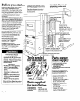
PRODUCTS Coin-Operated Stacked Dryers Electric /IMPORTANT: IRead and save 1the-B instructions. Important: *Read these instructions before you start to install the dryers. *Save Installation Instructions for local electrical inspectors use. l Keep Installation Instructions for future reference. windows and raised handles not available on all models. VI3 Part No. 3390148 Rev.
Before vou start a - --~ - . .a Protection from weather: Pro1 )er operation requlres temperah 1res above 45°F (7.2%). The wiring diagram Is locate< I inslde the control panel and acces panels. Check location where dryers will be used. Proper installation ls your responsibility. The dryers must not be installed or stored In an area where they will be exposed to water and/or weather. Make sure you have everything necessary for correct installation.
Electrical requirements. OBSERVE AU GOVEdNlNG AND ORDINANCES. COdES Electrical Shock Hazard . Electrical ground Is required on this appliance. . If cold water pipe Is interrupted by plastic, non-metallic gaskets, or other insulating materials, Do Not use for grounding. . Do Not ground to a gas pipe. . Do Not modify the power supply cord plugs. iflplugs will not fit the outlets, have proper outlets installed by a qualified electrician. . Use new 30-ampere power supply cord kits.
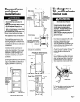
A. gw;(;)eundlw (green yellow If local codes permlt c01 lnection of cabinet-grounding concjuctors to the neutral wires of the FBower supply 1cords: ,, wlth stripes) 1exte ,nal grounding Figure 3 *Grounded cold water pipe must have metal continuity to electrical ground and not be interrupted by plastic, rubber or other electrical lnsulatin connectors such as hoses, 8 i ngs. washer or gaskets water meter or pump).
B 3. Attach a 3/4’, U.L.-listed strain relief to each dryer through the power supply cord holes. (See Flgure 6.) Tlghten each strain relief firmly to cabinet. Place a power supply cord or direct wlre through each strain relief. Tlghten screws firmly. If loc:l codes DO NOT permit cablnetgroundlng to the neutral wires of the power supply cords: metal cold water 1. Disconnect the power pipe 1 supply. Bumps on grounllng clamp must contact pipe. I 2. Attach a 3/4’. U.L.
Exhaust reqdrements Exhaust materials supplied. are not Fire Hazard l Do Not use non-metal, flexible duct. l Do Not use metal duct smaller than four Inches in diameter. l Do Not use exhaust hoods with magnetic latches. Improper air supply for exhaustlng may result in a fire. l Check that exhaust system is not longer ttian specified. Exhaust systems longer than specified will: - Accumulate Ilnt. - Shorten the life of the product.
Exhaust duct connectSor: Each exhaust duct should enter the maln duct at an angle pointing In the dlrectlon of the airflow. Ducts enterlng from the opposlte side should be staggered to reduce the exhausted air from lnterferlng with the other ducts. The maxlmum angle of each duct entering the main duct should be nc more than 30”. Prod?! Damage Keep air openings free of dry-cleaning fluid fumes. Fumes create acids whtch,when drawn through the dryer heating units, can damage dryers and loads being dried.
Internal \ exhaust duct 3.1 Remove duct tape from In .ernal exhaust duct and the straight duct. dryel rear Y 6. [Insert elbow end of duct pieces through the side opening. Reach through the access panel openlng and attach elbow to the Internal exhaust duct. Check the length of stralght duct extending out the side of the cabinet. If duct extends too far to make the exhaust duct connection, mark a line around the stralght duct one Inch out from the cabinet.
Recessed area and closet installations Cochange to a 30, or 60-minute :iming cam Closet vieqnr Side view ,< / I 0’-I, 0’ /Additional clearances for wall. door and ) floar moldings may be required. ddiial XC0 inlay be eded for xhausl elbow. Fire Hazard Dryers MUST be exhausted to outslde. Failure to do so may result in a fire. l Do Not exhaust dryers into a chimney, furnace cold air duct, attic or crawl space, or any other duct used for venting.
Now start.. . With dryers in laurldry I Il. area. Check that each leg is approximately 1 inch frc)rn base. ‘2. Wipe the Interior of the drums thoroughly with a damt ) cloth. 4. insert a narrow, flat-blade screwdriver under the timing cam near the clock shaft. Gently lift cam straight up and off shaft making sure that the ‘V-shaped notch clears the ratchet tooth. :3 . Install coin vaults and Ic cks (not supplled) into meter cc se openings. 14 5. Place new cam (hub side down) over clock shaft.
ilO. ib I : Make electrical connection. See / ‘Electrical requirements,’ Page 3. Turn on electrIcal Move dryers to their permanent location. supply. The installation of your electric dryers now complete. ‘11. Check levelness of dryers by placing a carpenter’s level on top of the dryers or collar, first side to side, then front to back. If dryer is not level, adjust the front legs up or down. Make the final check with the level. power 15 is n Check to make sure you have ? all your tools.
Moving the: dryers to a new locatton.. . If dryers do not operate properly.. . I Check the following sure thcrt: 1, Electric supply l to be l Is.connected. 2. Circuit breakers fuses blown. are not tripped or 3. Doors are closed. 4. Controls are set in a running ‘ON’ position. or \me whirlpod Consumer Assistance i Center will answer any questions 1about operating or maintainlng your idryers not covered in your Operating i Instructions.