033_03_NEW SELECTOR SWITCH 07/2007 Instructions for installation, use and maintenance ELECTRIC KETTLES AGB AGB AGB AGB AGB 372/WP · AGB 375/WP 377/WP · AGB 384/WP 386/WP · AGB 390/WP 392/WP · AGB 396/WP 399/WP · AGB 401/WP
INDEX Models and dimensions page 3 Commissioning and testing pag.
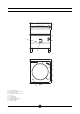
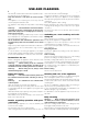
Dimensions 5 2 0 1 2 6 1 4 3 C F 2 E S T C E F 1 2 3 4 5 6 Technical data plate Hot water connection to 10 mm Electrical connection Cold water connection to 10 mm Selector Operation light Pressure gauge Cooking vat drainage tap Vat water feed tap Jacket level tap 033-03 - Electric kettles 3
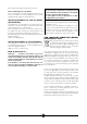
Controls 2 2 1 1 1 2 0 1 2 Off 50 % power 100 % power Only for pressure kettles: Valve and position of relief valve: Closed valve 033-03 - Electric kettles Open valve 4
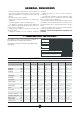
GENERAL REMINDERS - Read the warnings contained in this manual carefully as they provide important information concerning safety during the installation, use and maintenance of the appliance. - Keep these instructions carefully! - Only personnel trained for its specific use should use the equipment. - Keep the appliance under control during use. - The appliance should be used only for the purpose for which it has been specifically designed; other uses are improper and hence dangerous.
Construction - - - Main structure in steel with 4 adjustable height feet. Panels in stainless steel AISI 304, thickness 15-20/10. Cooking vat in stainless steel AISI 316, thickness 20/10. Chrome-plated brass drainage tap. Double wall lid in stainless steel, hinged and spring balanced in all opening positions. Jacket and lining in stainless steel AISI 304, thickness 15-20/10. Heating system comprising shielded heating elements made from “Incoloy-800” alloy with boiler and steam circulation.
ded to make the connection to the electrical power supply must be provided by the installer. The power cable shall be of the kind described in the paragraph “Technical data" and shall be resistant to oil. The power terminal board can be reached by removing the lower front panel (unloose the screws). The cable fastener is on the lower right-hand side. The cable must be fed in from beneath the clamp. The individual wires are then fastened to the corresponding terminals of the terminal board.
USE AND CLEANING Warnings and hints for user This manual contains all the instructions required for a proper and safe use of our appliances. Keep the manual in a safe place for future consultation! This appliance is for catering use, hence they must be used only by trained kitchen staff. The appliance must always be kept under control during use.
Rinse always thoroughly and dry with a soft cloth. Notes regarding the pressure kettles: Do not use detergents containing high percentages of ammonia and sodium to clean the lid gasket, as it could be damaged and its tightness quickly affected. Special procedures in case of prolonged inactivity If the appliance is to stand idle for any length of time (e.g. holidays or seasonal closing), it must be cleaned thoroughly, leaving not traces of food or dirt.
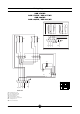
Wiring diagrams AGB 372/WP AGB 375/WP / AGB 377/WP AGB 396/WP AGB 399/WP / AGB 401/WP 2 4 2 6 4 6 R1 1 4 6 2 4 R1 1 3 R1 5 1 3 1 5 3 5 6 mA 2 3 R1 1 2 3 4 5 6 5 PE L1 L2 L3 230V 3 A2 A2 C1 C1 A1 A1 L2 L1 TL 5 2 1 3 4 SE mA TS 1 2 3 4 5 6 P3 P1 P2 2 1 0 L1 L2 L3 N 5 PE P3 400V 3N TL L1 L2 TS C1 SE R1 mA Working thermostat Orange operation light Green operation light Safety thermostat Electromagnetic switch Three position selector/switch He
Wiring diagrams AGB 384/WP / AGB 386/WP AGB 390/WP / AGB 392/WP R1 R1 C1 R1 C2 R1 C1 C2 L2 L1 5 4 1 3 SE P3 PL P1 mA TL L1 L2 L3 LR TS LA N 400V 3N 1 2 8 3 9 4 5 6 7 SL 10 = BULBO TERMOSTATO R1 R1 R1 Only for mod.
WARNING DUE TO ITS POLICY OF CONTINUAL PRODUCT IMPROVEMENT, THE MANUFACTURER RESERVES THE RIGHT TO MAKE ANY CHANGES DEEMED NECESSARY. THE MANUFACTURER CANNOT BE HELD RESPONSIBLE IF THE INSTRUCTIONS CONTAINED IN THIS MANUAL ARE NOT OBSERVED. THIS DOCUMENTATION IS ONLY INTENDED FOR QUALIFIED TECHNICIANS WHO ARE AWARE OF THE RESPECTIVE SAFETY REGULATIONS. WHIRLPOOL EUROPE srl V.