
Instruction for Use


GB7
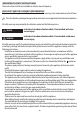
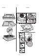
INSTALLATION - FITTING INSTRUCTIONS
Extractor hood installation (A): fumes are extracted and expelled to the outside through an exhaust duct xed to the ange C (bayonet coupling). Always shut
o the unused exhaust outlet with the plug D1 provided (if provided- bayonet coupling).
Important: some models are supplied with the upper hole B1 closed with a plug D1. Remove the plug to enable use.
Important! Not all models have rear drain hole B2.
Please note: if necessary, remove plastic piece D2 or D3 with the aid of pliers or a box cutter.
The use of a rear exit with this product is PROHIBITED within the European Community member states, the EFTA countries, in Turkey and all countries subject to
Commission Delegated Regulation (EU) No. 65/2014 and Commission Regulation (EU) No.66/2014.
Filter version installation (F): If it is not possible to duct fumes and steam to the outside, the hood can be used in the lter version by tting a carbon lter/s
(not supplied). In this way, fumes and steam are recycled through the front grille section positioned above the control panel.
Check the position of the extraction/lter selector (inside the hood) G.
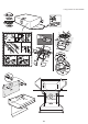
Fixing to the wall - Place the hood against the wall (or use the template H, if provided) and, using a pencil, mark the holes (3or4Ø8mm holes), drill them, insert
the rawlplugs J in the holes and 2 screws K in the top holes. Remove the grille and hang the hood on the 2 screws. Next, from inside, insert the third (and fourth)
screws L and screw them all down.
Fixing to the wall unit - Position the hood (or use the template H, if provided) and, using a pencil, mark the 4Ø6mm holes to be drilled on the bottom of the wall
unit.
Fix the hood in place with 4 screws M from inside the wall unit.
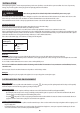
DESCRIPTION AND USE OF THE HOOD
Control panel
Light: move the switch to the right or press the next button to switch on.
Extraction speed: move the switch to the right or press the next button to increase extraction speed.
Grease lter - can be one of the following types:
Paper lter: must be replaced once a month or, if the top side is coloured, when the colour shows through the holes in the grille.
Metal lter: must be washed once a month by hand or in a dishwasher, using a quick wash cycle with a low temperature.
To access the grease lter open the grille using the spring release catches E1 or E2 or E3 and release it from the retainers R1 or R2.
The self-supporting metallic lter has no support grille. To remove it, pull the spring release handles E1 backwards and remove the lter downwards.
Important! Over time, the metallic lter may become opaque; this in no way aects its ltering capacity.
Carbon lter - can be one of the following types:
Shaped V1: Remove the cover W by turning the knobs O through 90°.
Insert the carbon lter inside the special housing and secure it in place by turning the knob O through 90°, then close the cover.
Replace every 4 months.
Rectangular V2: insert the rear edge rst T and then the front (U) - replace every 6 months.
Circular V3: Bayonet coupling. Position the lter in the centre so that it covers the motor-protection grille, make sure that the reference mark X1 or X2 or X3 or X4
on the carbon lter is aligned with the the reference mark Y on the fan shroud, then turn clockwise; to remove, turn anti-clockwise, if provided with a tab Z
remember to lift it up slightly rst.
Replace every 4 months.
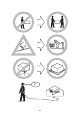
Replacing lamps
Remove the lters then remove the burnt-out bulb.
Use E14 2,5W max, LED lamps only. For more details, check enclosed leaet “ILCOS D” (alfanumeric position “1e”).
Ret the lters.