
Troubleshooting guide

TECH SHEET - DO NOT DISCARD PAGE 3
FOR SERVICE TECHNICIAN'S USE ONLY PART NO. 326038065
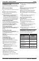
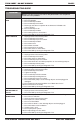
DIAGNOSTIC TEST
The control must be in the off state before
pressing the touchpad sequence to start the
test.
Starting the Test Mode
■
Push the START/OFF button to turn washer
off.
■
Unplug washer or disconnect power.
■
Plug in washer or reconnect power. All
LEDs should blink twice.
■
Within 10 seconds, simultaneously press
TEMPERATURE and WATER LEVEL
buttons. The WATER LEVEL LED will stay
on and all other LEDs should be off. If any
other LEDs are on, the starting procedure
has failed. Repeat the starting procedure.
Stopping the Test Mode
To exit the Components Test routine at any
time, press the START/OFF button or unplug
washer. When the START/OFF button is
pressed during Test Mode, the electronic
control switches to Standby Mode.
Test Program Control
In order to advance to the next step of the test
procedure, press the CYCLE SELECTOR
button.
Last Error Occurred
To display the last error that occurred,
simultaneously press the WATER LEVEL and
CYCLE SELECTOR buttons.
LED Test
Press the TEMPERATURE button. All LEDs
should be on.
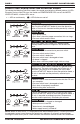
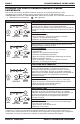
Component Tests
Pressure Switch (Medium Level)
and Cold Water Valve Test
■
Press the CYCLE SELECTOR button.
■
The Super Wash LED comes on.
■
The cold water valve is activated.
■
The pressure switch opens for a
Medium level fill task.
■
When the fill is complete, the Super
Wash LED flashes.
Pressure Switch (High Level)
and Hot Water Valve Test
■
Press the CYCLE SELECTOR button.
■
The Normal LED comes on.
■
The hot water valve is activated.
■
The pressure switch opens for a High
level fill task.
■
When the fill is complete, the Normal
LED flashes.
Motor Test
NOTE: To bypass this test and continue to the
next component test, press the CYCLE
SELECTOR button twice.
■
Press the CYCLE SELECTOR button.
■
The Express Wash LED comes on.
■
The motor begins a 15-minute agitation
task.
■
When the agitation is complete, the
Express Wash LED flashes.
Drain Pump and Brake Actuator
(on traction) Test
■
Press the CYCLE SELECTOR button.
■
The Gentle LED comes on.
■
The brake actuator and pump are
activated.
■
After 20 seconds, the pressure switch
opens and the motor begins a
10-minute spin cycle.
■
When the spin cycle is complete, the
Gentle LED flashes.
COMPONENT CONTINUITY TEST
Disconnect the wire harness and measure
resistance using the following table:
COMPONENT RESISTANCE
Wire Harness continuity
Power Cord continuity
Hot Water Valve
890–1090 Ω
Cold Water Valve
890–1090 Ω
Motor black/white and
red terminals
5.32–6.12 Ω
Motor black/white and
yellow terminals
5.32–6.12 Ω
Drain Pump
24–28 Ω
Brake Actuator –
on traction
710–869 Ω
Brake Actuator – at rest
403–493 Ω