KAC-46 TECHNICAL EDUCATION 27˝ & 30˝ ELECTRIC BUILT-IN MICROWAVE/OVEN COMBINATION MODELS: KEMS378S & KEMS308S JOB AID 4317410
FORWARD This KitchenAid Job Aid “27˝ & 30˝ Electric Built-In Microwave/Oven Combination” (Part No. 4317410), provides the In-Home Service Professional with information on the installation, operation, and service of the 27˝ & 30˝ Electric Built-In Microwave/Oven Combination. For specific information on the model being serviced, refer to the “Use and Care Guide,” or “Tech Sheet” provided with the oven.
TABLE OF CONTENTS Page GENERAL .............................................................................................................................. 1-1 Oven Safety ....................................................................................................................... 1-1 Model & Serial Number Designations ................................................................................ 1-3 Model & Serial Number Label And Tech Sheet Locations..........................................
Page COMPONENT TESTING ........................................................................................................ 5-1 UPPER OVEN COMPONENTS ......................................................................................... 5-1 Humidity Sensor ............................................................................................................. 5-1 Cavity Thermostat ..........................................................................................................
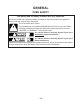
GENERAL OVEN SAFETY Your safety and the safety of others are very important. We have provided many important safety messages in this manual and on the appliance. Always read and obey all safety messages. This is the safety alert symbol. This symbol alerts you to potential hazards that can kill or hurt you and others. All safety messages will follow the safety alert symbol and either the word “DANGER” or “WARNING.
PRECAUTIONS TO BE OBSERVED BEFORE AND DURING SERVICING TO AVOID POSSIBLE EXPOSURE TO EXCESSIVE MICROWAVE ENERGY a. Do not operate or allow the oven to be operated with the door open. b. Make the following safety checks on all ovens to be serviced before activating the magnetron or other microwave source, and make repairs as necessary: 1. Interlock Operation 2. Proper Door Closing 3. Seal and Sealing Surfaces (Arcing, Wear and Other Damage) 4. Damage to or Loosening of Hinges and Latches 5.
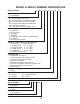
MODEL & SERIAL NUMBER DESIGNATIONS MODEL NUMBER K EM PRODUCT GROUP K = KITCHENAID PRODUCT IDENTIFICATION EB = ELECTRIC BUILT-IN OVEN EH = ELECTRIC BUILT-IN HI SPEED COMBO EM = ELECTRIC BUILT-IN MICRO COMBO EW = ELECTRIC WARMING OVEN/DRAWER GB = GAS BUILT-IN OVEN GM = GAS BUILT-IN MICRO COMBO OVEN MERCHANDISING SCHEME A = ARCHITECT C = FLUSH LOOK D = DRAWER I = IMPERIAL N = INTERNATIONAL COLLECTION EUROPEAN S = SUPERBA V = VBL PRO LINE SERIES CAPACITY / SIZE / SERIES / CONFIGURATION 1ST POSITION 2ND POSIT
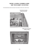
MODEL & SERIAL NUMBER LABEL AND TECH SHEET LOCATIONS The Model/Serial Number label and Tech Sheet locations are shown below.
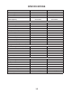
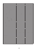
SPECIFICATIONS Model Number KEMS378SBL, BT, SS, WH KEMS308SBL, BT,SS,WH MW/BI Combo MW/BI Combo Size - Configuration 27˝ 30˝ Feature Level/Series Superba Superba KEMC377KBL/KEMC378KBL/ KEHC379JBL KEMC307KBL/KEMC308KBL/ KEHC309JBL Overall Height 42˝ 42˝ Overall Width 26-3/4˝ 29-3/4˝ 26˝ 26˝ Depth w/Door Open 90° 43-3/4˝ 43-3/4˝ Door Swing 15-3/8˝ 15-3/8˝ Cutout Height (Measure or Min/Max) 41-1/4˝ 41-1/4˝ Cutout Width (Measure or Min/Max) 25-1/2˝ 28-1/2˝ Cutout Depth (Measure o
Model Number KEMS378SBL, BT, SS, WH KEMS308SBL, BT,SS,WH Cleaning System Self Cleaning Self Cleaning Main Oven Liner Finish Blue Porcelain Blue Porcelain Main Oven Volume (cu ft) 3.6 4.
INSTALLATION INFORMATION INSTALLATION REQUIREMENTS TOOLS AND PARTS • Recessed installation area must provide complete enclosure around the recessed portion of the oven. • Grounded electrical supply is required. See “Electrical Requirements,” page 2-2. • Electrical supply junction box should be located 3˝ (7.6 cm) maximum below the support surface when the oven is installed in a wall cabinet. A 1˝ (2.
Cabinet Dimensions 27˝ (68.6 cm) and 30˝ (76.2 cm) Ovens It is not recommended to ground to a gas pipe. Check with a qualified electrical installer if you are not sure the oven is properly grounded. It is not recommended to have a fuse in the neutral or ground circuit. This oven must be connected to a grounded metal, permanent wiring system.
• Do not cut the conduit. The length of conduit provided is for serviceability of the oven. • A UL listed or CSA approved conduit connector must be provided. • If the house has aluminum wiring follow the procedure below: 1. Connect a section of solid copper wire to the pigtail leads. 2. Connect the aluminum wiring to the added section of copper wire using special connectors and/or tools designed and UL listed for joining copper to aluminum.
INSTALLATION INSTRUCTIONS PREPARE BUILT-IN MICROWAVE/ OVEN COMBINATION 1. REMOVE OVEN DOOR IMPORTANT: Use both hands to remove oven door. 1. Open the oven door. 2. Locate the oven door latches in both corners of the oven door, and rotate the latches forward to the unlocked position. Decide on the final location for the oven. Locate existing wiring to avoid drilling into or severing wiring during installation. WARNING Excessive Weight Hazard Use two or more people to move and install oven.
MAKE ELECTRICAL CONNECTION Electrical Connection Options Chart WARNING If your home has: Go to section: 4-wire 4-wire Cable from Home Power Supply ½" (1.3 cm) 3-wire Electrical Shock Hazard Disconnect power before servicing. Use 8 gauge solid copper wire. Electrically ground oven. Failure to follow these instructions can result in death, fire, or electrical shock. ½" (1.3 cm) 4-Wire Cable from Home Power Supply IMPORTANT: Use the 4-wire cable from home power supply in the U.S.
INSTALL OVEN 3-Wire Cable from Home Power Supply - U.S. Only IMPORTANT: Use the 3-wire cable from home power supply where local codes permit a 3-wire connection. A B C WARNING Excessive Weight Hazard Use two or more people to move and install oven. Failure to do so can result in back or other injury. G H D 1. Using 2 or more people, lift oven partially into cabinet cutout using the oven opening as an area to grip. NOTE: Push against seal area of oven front frame when pushing oven into cabinet.
4. Securely fasten oven to cabinet using the #8-14 x 1˝ screws (2 for single oven, 4 for double oven) provided. Insert the screws through holes in mounting rails. Do not overtighten screws. 10. Check that the door is free to open and close. If it is not, repeat the removal and installation procedures. See “Remove Oven Door,” page 2-4. 11. Reconnect power. 12. Display panel will light briefly, and “PF” should appear in the display. 13.
Check Operation of Microwave Oven 1. Fill a microwave-safe container with 1 cup (250 mL) of water and place container inside microwave oven. Close door firmly. 2. Set microwave oven cook time to “2:00” minutes. 3. Touch START. The interior microwave oven light should be on, and the remaining cooking time should be displayed in the upper oven display. If microwave does not operate, check the following: • Household fuse is intact and tight; or circuit breaker has not tripped. • Electrical supply is connected.
PRODUCT OPERATION % OZ FC LBS POWER TIMER MAXIMUM TIME REMAINING % OZ FC LBS POWER TIMER MAXIMUM TIME REMAINING ELECTRONIC OVEN CONTROL CONTROL LOCK DONENESS The Control Lock shuts down the control panel keys to avoid unintended use of the oven. The Control Lock will remain set after a power failure, if set before the power failure occurs. When the control is locked, only the TIMER SET/START, TIMER OFF and OVEN LIGHT keys will function.
SABBATH MODE CONVECTION BROIL The Sabbath Mode sets the oven to remain on in a bake setting until turned off. A timed Sabbath Mode can also be set to keep the oven on for only part of the Sabbath. When the Sabbath Mode is set, only the number and start keys will function, no tones will sound, and the displays will not show messages or temperature changes. The heat sources icons will appear lit on the lower oven display throughout the Sabbath Mode.
TEMPERATURE PROBE DEHYDRATING (on convection models, closed door) WARNING Dehydration is a method used to preserve food. Various factors, such as the quality of the fresh food, pretreatment techniques, the size and thickness of the food, and the climate may affect the finished product. During dehydration, heat is used to force out moisture and air circulation is used to carry the moisture away. Refer to a reliable book or source for complete information about dehydrating and preserving foods.
— NOTES — 3-4
COMPONENT ACCESS This section instructs you on how to service each component inside the KitchenAid 27˝ & 30˝ Electric Built-In Microwave/Oven Combination. The upper oven components and their locations are shown below. The lower oven component locations are shown on page 4-27.
REMOVING THE USER INTERFACE AND THE OVEN & MICROWAVE CONTROL BOARD ASSEMBLIES WARNING c) Disconnect the two ribbon cable connectors from the user interface and remove the interface. Electrical Shock Hazard Disconnect power before servicing. Replace all parts and panels before operating. Failure to do so can result in death or electrical shock. 1. 2. 3. User Interface Ribbon Cables 5. Unplug oven or disconnect power.
REMOVING THE HUMIDITY SENSOR AND THE CAVITY THERMOSTAT WARNING MW Relay Board Humidity Sensor 5. Electrical Shock Hazard Disconnect power before servicing. Replace all parts and panels before operating. Failure to do so can result in death or electrical shock. 1. 2. Cavity Thermostat To remove the humidity sensor: a) Remove the two screws from the humidity sensor. Humidity Sensor Screws Unplug oven or disconnect power.
REMOVING THE CONTROL POWER AND THE MICROWAVE LIGHT TRANSFORMERS WARNING Control Power Transformer MW Light Transformer 5. Electrical Shock Hazard Disconnect power before servicing. Replace all parts and panels before operating. Failure to do so can result in death or electrical shock. 1. 2. Unplug oven or disconnect power. Open the microwave oven door, remove the two flat-head screws from the bottom of the control panel frame, and remove the frame.
REMOVING THE CONVECTION THERMOACTUATOR AND THE WIDE INTERFACE BOARD WARNING Convection Thermoactuator WIDE Interface Board 5. Electrical Shock Hazard Disconnect power before servicing. Replace all parts and panels before operating. Failure to do so can result in death or electrical shock. 1. 2. Wire Connectors Unplug oven or disconnect power. Open the microwave oven door, remove the two flat-head screws from the bottom of the control panel frame, and remove the frame. Thermoactuator Screws 6.
REMOVING THE MONITOR FUSE AND THE MICROWAVE APPLIANCE MANAGER WARNING Monitor Fuse Microwave Appliance Manager 5. Electrical Shock Hazard Disconnect power before servicing. Replace all parts and panels before operating. Failure to do so can result in death or electrical shock. 1. 2. Monitor Fuse BR BR Unplug oven or disconnect power. Open the microwave oven door, remove the two flat-head screws from the bottom of the control panel frame, and remove the frame. Fuse Holder Screw 6.
REMOVING THE MICROWAVE DOOR INTERLOCK SWITCHES AND THE CAVITY LIGHT WARNING Cavity Light Sec. Interlock Sw. 5. Electrical Shock Hazard Disconnect power before servicing. Replace all parts and panels before operating. Failure to do so can result in death or electrical shock. 1. 2. Unplug oven or disconnect power. Open the microwave oven door, remove the two flat-head screws from the bottom of the control panel frame, and remove the frame.
6. To remove the primary or monitor interlock switch: a) Place the blade of a flat-blade screwdriver between the switch body and the holder. Twist the blade until the switch is free of the tabs, and remove the switch from the holder. c) Monitor (rear): Disconnect the red (COM) and blue (N.C.) wires from the switch terminals. RD (COM) BU (N.C.) Monitor Interlock Switch Monitor Interlock Switch 7.
REMOVING THE MAGNETRON THERMOSTAT AND THE MAGNETRON WARNING 4. To remove the magnetron thermostat: a) Disconnect the two wire connectors from the thermostat terminals. b ) Remove the two screws from the thermostat and remove the thermostat. Wire Connectors Electrical Shock Hazard Disconnect power before servicing. Replace all parts and panels before operating. Failure to do so can result in death or electrical shock. 1. 2. 3. Magnetron Thermostat Screw (1 of 2) Unplug oven or disconnect power.
d) Remove the eight screws from the top right side cover and remove the cover. f) IMPORTANT: Touch a screwdriver shaft to the two filament connectors and chassis ground. g) Disconnect the two red filament wires from the magnetron terminals. h) Remove the four screws from the magnetron, move the end of the microwave relay board bracket out of the way, and remove the magnetron.
REMOVING THE MAIN L1 FILTER, MAIN L2 FILTER, AND GRILL THERMOSTAT WARNING Main L2 Filter Electrical Shock Hazard Disconnect power before servicing. Replace all parts and panels before operating. Failure to do so can result in death or electrical shock. 1. 2. 3. 5. Unplug oven or disconnect power. Remove the oven from its mounting location (see “Installation Information” in Section 2) and pull it forward so that you can access the top cover.
c) Disconnect the wires from the main L1 filter board as follows: White at P31 (to 3-pin plug) Black at P32 Brown at P33 White at P34 d) Remove the mounting screw and remove the board from the bracket. c) Disconnect the wires from the main L2 filter terminals. Main L2 Filter P32 BK P31 WH GN/YL (GND) Screw RD (PLUG) WH (PLUG) 4 P34 WH BK (THERMOSTAT) 7. Main L1 Filter 6.
REMOVING THE MAGNETRON FAN MOTOR & THE INVERTER WARNING 5. Upper Rear Cover (10 Screws) Electrical Shock Hazard Disconnect power before servicing. Replace all parts and panels before operating. Failure to do so can result in death or electrical shock. 1. 2. 3. Remove the ten screws from the upper rear cover of the oven and remove the cover. Unplug oven or disconnect power.
c) Remove the magnetron fan motor housing assembly and set it on top of the oven. d) Disconnect the two black wires from the magnetron fan motor terminals. g) Pull the blower off the magnetron fan motor shaft. Motor Shaft Magnetron Fan Blower Magnetron Fan Motor Wires 7. e) Remove the three screws from the magnetron fan motor housing and separate the sections. To remove the inverter: a) Remove the two top screws from the outer convection cover at the rear of the oven. Outer Convect.
c) IMPORTANT: Touch a screwdriver shaft to the two filament connectors and chassis ground. d) Disconnect the two filament wires from the magnetron terminals. e) Remove the screw from the green/yellow ground wire.
REMOVING THE CONVECTION THERMISTOR AND GRILL ELEMENT WARNING 5. Remove the seven screws from the outer convection cover and remove the cover. Outer Convect. Cover (7 Screws) Electrical Shock Hazard Disconnect power before servicing. Replace all parts and panels before operating. Failure to do so can result in death or electrical shock. 1. 2. 3. Unplug oven or disconnect power.
c) Disconnect the convection thermistor connector from appliance manager connector P6 and remove the thermistor. c) Open the microwave oven door. d) Twist the front grill element support 90° in either direction and remove it from the cavity slot. Front MW Grill Element Support e) Lower the front of the grill element, pull the element terminals out the back holes of the cavity, and remove the element. Conv. Therm.
REMOVING THE LOWER OVEN APPLIANCE MANAGER WARNING AC Wiring Conduit Connector Upper Left Side Cover (8 Screws) Electrical Shock Hazard Disconnect power before servicing. Replace all parts and panels before operating. Failure to do so can result in death or electrical shock. 1. 2. 3. Unplug oven or disconnect power. Remove the oven from its mounting location (see “Installation Information” in Section 2) and pull it forward so that you can access the top cover.
7. 8. Disconnect the wire connectors from the lower oven appliance manager board pins. The wire connector colors are as follows: T1 = PK/WH, PK T2 = 2 PK T3 = OR, RD, YL, BU T4 = 2 BK P9 = GY, BK P8 = BK, OR, GY, YL, BK/WH P7 = VI, WH P2 = 2 VI, OR, WH P1 = PK, BR, TN P5 = GN, PK/WH P6 = BR, OR, YL, BU Remove the four lower oven appliance manager housing screws and remove the housing assembly. T1 P6 P5 9.
REMOVING THE LINE FUSE HOLDER & LOWER OVEN LIGHT TRANSFORMER WARNING 4. Electrical Shock Hazard Disconnect power before servicing. Replace all parts and panels before operating. Failure to do so can result in death or electrical shock. 1. 2. 3. To remove the line fuse and holder: a) Pull the fuse out of the holder clips. b) Disconnect the two black wires from the fuse holder terminals. c) Remove the two screws from the fuse holder and remove it.
REMOVING THE AC TERMINAL BLOCK 4. Remove the nuts from the black, white, and red wires and remove the wires from the terminal block studs. Remove the two mounting screws from the terminal block and remove it from the side cover. 5. Electrical Shock Hazard Disconnect power before servicing. Replace all parts and panels before operating. Failure to do so can result in death or electrical shock. 3. Unplug oven or disconnect power.
REMOVING THE CONVECTION THERMOSTAT, RING ELEMENT, AND FAN MOTOR WARNING 5. Remove the seven screws from the outer convection cover and remove the cover. Outer Convect. Cover (7 Screws) Electrical Shock Hazard Disconnect power before servicing. Replace all parts and panels before operating. Failure to do so can result in death or electrical shock. 1. 2. 3. Unplug oven or disconnect power.
7. To remove the convection ring element: a) Disconnect the two wires from the ring element terminals. b) Remove the six screws, (including the cavity thermostat clip), from the inner convection cover, remove the cover, and turn it over. 8. To remove the convection fan motor: a) Disconnect the two wires from the fan motor terminals. b) Remove the six screws, (including the cavity thermostat clip), from the inner convection cover, remove the cover, and turn it over.
REMOVING THE TURNTABLE MOTOR 5. WARNING Remove the four screws from the front control subpanel, remove the subpanel assembly, and lay it on top of the oven. Front Subpanel Screws Electrical Shock Hazard Disconnect power before servicing. Replace all parts and panels before operating. Failure to do so can result in death or electrical shock. 1. 2. 3. 6. Unplug oven or disconnect power.
7. 8. 9. Unhook and remove the AC wiring conduit connector from the back of the upper left side cover. Remove the five screws from the upper left side cover and remove the cover. Remove the five screws from the upper right side cover and remove the cover. 11. Set the control subpanel assembly in its place on the front of the oven and hold it in place so it does not fall. NOTE: You will need something approximately 12-13˝ long to prop up the front of the microwave oven in step 12. 12.
14. Lower the motor as far as possible, pull the turntable coupler off the motor shaft and remove the motor from the oven. 15. Remove the cardboard insulator and the round rubber spacer from the motor. 16. Disconnect the two wire connectors from the motor terminals.
Lower Oven Components Blower Speed Resistor Blower Motor Lower Temperature Sensor (On Oven Liner) Blower Door Latch Assembly Oven Shutdown Thermal Cutoff (non-resettable) Halogen Light Meat Probe Convection Ring Element IN/OUT Broil Element Convection Fan Motor Oven Door Glass Door Gasket Halogen Lights Hidden Bake Element 4-27
REMOVING THE DOOR LATCH ASSEMBLY 7. WARNING Remove the two screws from the door latch assembly, pull the latch assembly back to remove the latches from the cutouts, and then lift and pull it forward so that you can access the wiring. Electrical Shock Hazard Disconnect power before servicing. Replace all parts and panels before operating. Failure to do so can result in death or electrical shock. 1. 2. 3. 4. Door Latch Assembly Screws Unplug oven or disconnect power.
9. To remove the latch motor, remove the two motor screws from the bottom of the assembly. 10. To remove the door or latch switch, remove the bracket screw. NOTE: You will have to remove the latch motor (in step 9) to access the door or latch switch screws. Door Switch Screw Latch Switch Screw Latch Motor Screws REASSEMBLY NOTE: After you reinstall the door latch assembly in the oven, press the two covers back down into place.
REMOVING THE BROIL ELEMENT AND THE OVEN TEMPERATURE SENSOR WARNING Broil Element Screws Electrical Shock Hazard Disconnect power before servicing. Replace all parts and panels before operating. Failure to do so can result in death or electrical shock. 1. 2. b) Pull the broil element forward until you can access the wire terminals. c) Disconnect the orange and blue wire connectors from the broil element terminals and remove the element. Unplug oven or disconnect power. Open the lower oven door.
4. To remove the oven temperature sensor: a) Remove the screws from the sensor bracket. e) Disconnect the sensor wire connector from the wiring harness. f) Push the sensor wire connector through the oven liner hole from the rear of the oven. Oven Liner Hole Temperature Sensor Screws Temperature Sensor Connector b) Remove the oven from its mounting location (see “Installation Information” in Section 2) and pull it forward so that you can access the top cover.
REMOVING THE CONVECTION RING ELEMENT AND THE CONVECTION FAN MOTOR WARNING 4. To remove the convection ring element: a) Remove the two screws from the element brackets. Ring Element Electrical Shock Hazard Disconnect power before servicing. Replace all parts and panels before operating. Failure to do so can result in death or electrical shock. 1. 2. 3. Unplug oven or disconnect power. Open the lower oven door. Remove the seven screws from the convection cover and remove the cover.
5. To remove the convection fan motor: a) Remove the 10mm hex nut from the convection fan blade (left-hand rotation) and remove the blade from the motor shaft. d) Remove the twelve screws from the lower rear cover and remove the cover. Lower Rear Cover (12 Screws) Convection Fan Blade Convection Fan Motor Fan Blade Nut b) Remove the three front screws from the convection fan motor. Front Convection Fan Motor Screws e) Disconnect the red and yellow wires from the convection fan motor terminals.
REMOVING A HALOGEN LIGHT ASSEMBLY AND THE MEAT PROBE JACK WARNING b) Unclip the lens from the socket and remove the lens. Electrical Shock Hazard Disconnect power before servicing. Replace all parts and panels before operating. Failure to do so can result in death or electrical shock. 1. 2. Lens Clip c) Remove the halogen bulb from the socket connector. Unplug oven or disconnect power. Open the lower oven door.
4. To remove the meat probe jack: a) Remove the nut from the meat probe jack. Remove Access Cover Meat Probe Jack Nut b) Remove the oven from its mounting location (see “Installation Information” in Section 2) and pull it forward so that you can access the meat probe jack access cover on the right side of the oven. d) Remove the meat probe jack from the right side cover. e) Disconnect the wires from the meat probe jack terminals.
REMOVING THE BLOWER ASSEMBLY, BLOWER SPEED RESISTOR, AND OVEN SHUTDOWN THERMAL CUTOFF WARNING Blower Electrical Shock Hazard Disconnect power before servicing. Replace all parts and panels before operating. Failure to do so can result in death or electrical shock. 1. 2. 3. Blower Speed Resistor 5. Unplug oven or disconnect power. Remove the oven from its mounting location (see “Installation Information” in Section 2) and pull it forward so that you can access the top cover.
7. To remove the oven shutdown thermal cutoff (TCO): a) Disconnect the two red wires from the TCO terminals. b) Remove the two mounting screws and remove the TCO.
REMOVING THE HIDDEN BAKE ELEMENT 5. WARNING 6. Disconnect the two red wires from the hidden bake element terminals. Remove the four screws from the hidden bake element cover. Hidden Bake Element Cover Screws Electrical Shock Hazard Disconnect power before servicing. Replace all parts and panels before operating. Failure to do so can result in death or electrical shock. 1. 2. 3. Red Wires 7. Unplug oven or disconnect power.
NOTE: When you remove the hidden bake element, press down on the front edge of the panel that is below the element so that it does not interfere with the removal. 10. Pull the hidden bake element out and remove it from the bottom of the oven. 11. Remove the two bracket screws from the hidden bake element and remove the bracket from the element.
REMOVING THE OVEN DOOR GLASS AND HANDLE 1. 2. Open the lower oven door. Raise the two door hinge tabs to the “unlocked” position. 3. 4. Door Hinge Tab Locked (Down) 5. 6. Close the oven door to within several inches, lift and pull out on the hinges, and remove them from the oven slots. Place the oven door front side down on a padded surface to protect the finish. Remove the two screws from each of the bottom corner glass holders and remove the holders.
c) Remove the four door handle bracket screws and remove the brackets and handle from the door. d) Slide the bottom edge of the outer oven door glass out of the door frame and remove the glass.
REMOVING THE OVEN DOOR GASKET 1. Remove the lower oven door (see the procedure on page 4-40). 2. 3. Remove the screw from the door gasket retainer and remove the retainer. Pull the door gasket clips out of the oven liner holes and remove the gasket.
COMPONENT TESTING UPPER OVEN COMPONENTS • Conduct a microwave energy test after performing any tests or repairs to the microwave oven. • Check that all wire leads are in the correct position before operating the microwave oven. • Grasp wire connectors when removing the wire leads from microwave to oven parts. • All testing must be done with an ohmmeter having a sensitivity of 20,000 ohms per volt DC or greater, and powered by at least a 9-volt battery. • Unplug oven or disconnect power.
WARNING Electrical Shock Hazard Disconnect power before servicing. Replace all parts and panels before operating. Failure to do so can result in death or electrical shock. MICROWAVE LIGHT TRANSFORMER CONVECTION THERMOACTUATOR Refer to page 4-4 for the procedure for accessing the microwave light transformer. 1. Unplug oven or disconnect power. 2. Disconnect one of the wires from the LINE (primary) and one from the LOAD (secondary) terminals. 3. Set the ohmmeter to the R x 1 scale. 4.
WARNING Electrical Shock Hazard Disconnect power before servicing. Replace all parts and panels before operating. Failure to do so can result in death or electrical shock. MICROWAVE DOOR INTERLOCK SWITCHES MONITOR FUSE COM N.O. Refer to page 4-6 for the procedure for accessing the monitor fuse. 1. Unplug oven or disconnect power. 2. Disconnect one of the wires from the fuse holder terminals. 3. Set the ohmmeter to the R x 1 scale. 4. Touch the ohmmeter test leads to the fuse holder terminals.
WARNING Electrical Shock Hazard Disconnect power before servicing. Replace all parts and panels before operating. Failure to do so can result in death or electrical shock. MAGNETRON THERMOSTAT MAGNETRON Filament Terminals Refer to page 4-9 for the procedure for accessing the magnetron thermostat. 1. Unplug oven or disconnect power. 2. Disconnect one of the wires from the magnetron thermostat terminals. 3. Set the ohmmeter to the R x 1 scale. 4. Touch the ohmmeter test leads to the thermostat terminals.
WARNING Electrical Shock Hazard Disconnect power before servicing. Replace all parts and panels before operating. Failure to do so can result in death or electrical shock. MAIN L1 & L2 FILTERS GRILL & CONVECTION THERMOSTATS Main L2 Filter 3 1 P34 Grill Thermostat 4 2 Convection Thermostat P33 Main L1 Filter P31 Refer to page 4-11 for the procedure for accessing the grill thermostat, and page 4-22 for the convection thermostat. 1. Unplug oven or disconnect power. 2.
WARNING Electrical Shock Hazard Disconnect power before servicing. Replace all parts and panels before operating. Failure to do so can result in death or electrical shock. MICROWAVE INVERTER BOARD MAGNETRON FAN MOTOR CN702 CN701 E701 Refer to page 4-13 for the procedure for accessing the magnetron fan motor. 1. Unplug oven or disconnect power. 2. Disconnect one of the wires from the magnetron fan motor terminals. 3. Set the ohmmeter to the R x 1 scale. 4.
WARNING Electrical Shock Hazard Disconnect power before servicing. Replace all parts and panels before operating. Failure to do so can result in death or electrical shock. GRILL ELEMENT LOWER OVEN LIGHT TRANSFORMER LINE (Primary) Terminals Grill Element LOAD (Secondary) Terminals Refer to page 4-16 for the procedure for accessing the grill element. 1. Unplug oven or disconnect power. 2. Disconnect one of the wires from the grill element terminals. 3. Set the ohmmeter to the R x 1 scale. 4.
WARNING Electrical Shock Hazard Disconnect power before servicing. Replace all parts and panels before operating. Failure to do so can result in death or electrical shock. MICROWAVE CONVECTION RING ELEMENT MICROWAVE CONVECTION FAN MOTOR Refer to page 4-22 for the procedure for accessing the microwave convection ring element. 1. Unplug oven or disconnect power. 2. Disconnect one of the wires from the convection ring element terminals. 3. Set the ohmmeter to the R x 1 scale. 4.
WARNING Electrical Shock Hazard Disconnect power before servicing. Replace all parts and panels before operating. Failure to do so can result in death or electrical shock. MEASURE OVEN INPUT CURRENT TURNTABLE MOTOR Connect an ammeter (Valhalla Scientific 2101 or equivalent recommended) to measure the input current of microwave oven when the power level is set to Level 10 at the touch panel. If more than 0.5A: The 900W inverter is probably OK. Check the magnetron. See Magnetron test on page 5-4.
LOWER OVEN COMPONENTS WARNING Electrical Shock Hazard Disconnect power before servicing. Replace all parts and panels before operating. Failure to do so can result in death or electrical shock. DOOR LATCH ASSEMBLY Refer to page 4-28 for the procedure for accessing the door latch assembly. NOTE: The door latch assembly components will be tested at the appliance manager board (see page 4-18). 1. Unplug oven or disconnect power. 2. Set the ohmmeter to the R x 1K scale. 3.
WARNING Electrical Shock Hazard Disconnect power before servicing. Replace all parts and panels before operating. Failure to do so can result in death or electrical shock. BROIL ELEMENT OVEN TEMPERATURE SENSOR Refer to page 4-30 for the procedure for accessing the broil element. NOTE: The broil element will be tested at the appliance manager board (see page 4-18). 1. Unplug oven or disconnect power. 2. Set the ohmmeter to the R x 1 scale. 3. Touch the ohmmeter test leads to the wire connectors.
WARNING Electrical Shock Hazard Disconnect power before servicing. Replace all parts and panels before operating. Failure to do so can result in death or electrical shock. CONVECTION RING ELEMENT CONVECTION FAN MOTOR Refer to page 4-32 for the procedure for accessing the convection ring element. NOTE: The convection ring element will be tested at the appliance manager board (see page 4-18). 1. Unplug oven or disconnect power. 2. Set the ohmmeter to the R x 1 scale. 3.
WARNING Electrical Shock Hazard Disconnect power before servicing. Replace all parts and panels before operating. Failure to do so can result in death or electrical shock. BLOWER MOTOR Refer to page 4-34 for the procedure for accessing the meat probe jack. NOTE: The meat probe jack will be tested at the appliance manager board (see page 4-18). 1. Unplug oven or disconnect power. 2. Set the ohmmeter to the R x 1 scale. 3. Touch the ohmmeter test leads to wire connectors P2-6 (WH) and P2-5 (OR).
WARNING Electrical Shock Hazard Disconnect power before servicing. Replace all parts and panels before operating. Failure to do so can result in death or electrical shock. BLOWER SPEED RESISTOR Refer to page 4-36 for the procedure for accessing the blower speed resistor. NOTE: The blower speed resistor will be tested at the appliance manager board (see page 4-18). 1. 2. 3. Unplug oven or disconnect power. Set the ohmmeter to the R x 1 scale.
WARNING Electrical Shock Hazard Disconnect power before servicing. Replace all parts and panels before operating. Failure to do so can result in death or electrical shock. HIDDEN BAKE ELEMENT 1. 2. 3. Unplug oven or disconnect power. Set the ohmmeter to the R x 1 scale. Touch the ohmmeter test leads to wire connectors T3-3 (RD) and T1-1 (RD). The meter should indicate between 26 and 30 Ω. T1 1 2 Refer to page 4-38 for the procedure for accessing the hidden bake element.
— NOTES — 5-16
DIAGNOSTICS & TROUBLESHOOTING WARNING Electrical Shock Hazard Disconnect power before servicing. Replace all parts and panels before operating. Failure to do so can result in death or electrical shock. DIAGNOSTICS IMPORTANT Electrostatic Discharge (ESD) Sensitive Electronics ESD problems are present everywhere. ESD may damage or weaken the electronic control assembly. The new control assembly may appear to work well after repair is finished, but failure may occur at a later date due to ESD stress.
Screen 1: A. Main clock hours display shows latch state in first display position, and door state in second position. B. Main clock minutes display show the model select state associated with control system. C. Main temperature display shows the cavity temperature. D. Lower text line shows software versions for appliance manager (AM), user interface (UI) and EEPROM version. Press key #6 to scroll to next screen. Screen 2: Screen displays programmed cavity size. Press key #6 to scroll to next screen.
WARNING Electrical Shock Hazard Disconnect power before servicing. Replace all parts and panels before operating. Failure to do so can result in death or electrical shock.
FAILURE ERROR (Leftmost (Rightmost MESSAGE/DESCRIPTION 2 Clock 2 Clock Digits) Digits) SUGGESTED CORRECTIVE ACTION PROCEDURE PROCEDURE: There are three sensors for the microwave. They are the Cavity Sensor, Ambient Sensor (integrated on the MW appliance manager), and Humidity Sensor. Before proceeding, press OFF, OFF, START to enter the Diagnostic mode. A. Press the number "6" key to transition to the Sensors screen. B. Verify in diagnostics the temperature readings on sensor. C.
FAILURE ERROR (Leftmost (Rightmost MESSAGE/DESCRIPTION 2 Clock 2 Clock Digits) Digits) SUGGESTED CORRECTIVE ACTION PROCEDURE UPPER OVEN UI IS NOT DISPLAYING THE AM SOFTWARE AND EEPROM VERSIONS A. Unplug oven or disconnect power. B. Open the back panels and make sure the P2 and U3 connectors are fully inserted on the microwave user interface and the wide interface board. Make sure the P1 connector on the wide interface board and the P10 connector on the microwave oven appliance manager are inserted.
FAILURE ERROR (Leftmost (Rightmost MESSAGE/DESCRIPTION 2 Clock 2 Clock SUGGESTED CORRECTIVE ACTION PROCEDURE Digits) Digits) FAILURE ERROR (Leftmost (Rightmost MESSAGE/DESCRIPTION 2 Clock 2 Clock SUGGESTED CORRECTIVE ACTION PROCEDURE Digits) Digits) COOK oven OVER TEMPERATURE E1 E2 CLEAN oven OVER TEMPERATURE PROCEDURE: Before proceeding, press OFF, OFF, START to enter the Diagnostic mode. A. If oven is off, turn oven on and inspect all of the elements, convect ring, bake and broil.
FAHRENHEIT (° F) TO CELSIUS (° C) CONVERSION KEYPADS Model select state The temperature is preset in Fahrenheit, however it can be changed to Celsius. To Change: Press OPTIONS and then “1” to toggle temperature between Fahrenheit and Celsius settings. When in Fahrenheit, “°F” follows the oven temperature. When in Celsius, “°C” follows the oven temperature.
MODES OFF BAKE PRE-B BAKE PRE-A BAKE SS CBAKE PRE-B CBAKE PRE-A CBAKE SS FBROIL PRE-B FBROIL PRE-A FBROIL SS INBROIL PRE-B INBROIL PRE-A INBROIL SS CBROIL PRE-B CBROIL PRE-A CBROIL SS CROAST PRE-B CROAST PRE-A CROAST SS BPROOF PRE-B BPROOF PRE-A BPROOF SS DEHYDRATE PRE-B DEHYDRATE PRE-A DEHYDRATE SS CLEAN • The magnetron output will be lower with lower line voltages. 1. Fill a glass beaker with 10 oz. (300mL) of tap water. Stir the water with a thermometer (digital recommended) and record the temperature.
WIRING DIAGRAM & STRIP CIRCUITS WIRING DIAGRAM SYMBOLS GROUND (CHASSIS) RELAY COIL PLUG WITH FEMALE CONNECTOR RELAY CONTACTS RECEPTACLE WITH MALE CONNECTOR NOTES: When replacing the electronic control, be sure to program the cavity size. See “Programming the Cavity Size” on page 6-7. Dots indicate connections or splices. Circuit shown in STANDBY/OFF mode with oven door closed.
STRIP CIRCUITS The following individual circuits are for use in diagnosis, and are shown in the ON position. Do not continue with the diagnosis of the appliance if a fuse is blown, a circuit breaker is tripped, or if there is less than a 240 volt power supply at the wall outlet.
BREAD PROOF PREHEAT B - BREAD PROOF PREHEAT A BREAD PROOF SS L2 N W L1 BK BK BK T4-3 T3-3 R T1-1 T1-2 R R/W P8-4 GY P8-1 OVEN SHUTDOWN THERMAL CUTOFF (NON-RESETTABLE) (105°C) (221°F) BAKE 200W R BLOWER GY M BLOWER SPEED RESISTOR CONVECT BAKE PREHEAT A - CONVECT BAKE SS N L1 BK BK BK T4-3 T4-4 W BK P8-1 BAKE 200W T3-3 R T3-1 BU L2 W R R OVEN SHUTDOWN THERMAL CUTOFF (NON-RESETTABLE) (105°C) (221°F) OUT BROIL 1450W CONV.
CLEAN BR N W DOOR SWITCH (ON LATCH ASSY) L1 BK BR OR BU T LATCH SWITCH (OPERATED BY MOTOR) P1-5 P1-7 P1-4 BK BK T4-3 BK BK P9-5 P8-1 T4-4 BAKE 2000W N L2 R T3-3 R T3-1 BUOUT BROIL 1450W BU T3-4 T1-1 T1-2 T2-1 T2-2 P9-2 OR IN BROIL 1800W OR R R/W R R/W GY M W R R W R OVEN SHUTDOWN THERMAL CUTOFF (NON-RESETTABLE) (105°C) (221°F) BLOWER W W M MOTOR LATCH P8-5 MWO FULL POWER - MWO VARIABLE POWER - MWO STEAM L1 BK LINE 20A BK FUSE BK LINE FILTER L1 P32 P33 MONITOR 20A FUSE B
MWO CRISP L2 L1 R BK LINE 20A BK FUSE BK LINE FILTER L1 P32 P33 MONITOR 20A FUSE BK BR BR BK MW APPLIANCE MANAGER MW LIGHT TRANSFORMER P2-6 P1-1 N MW APPLIANCE MANAGER W CAVITY LINE FILTER L1 THERMOSTAT BU W W W P1-2 P31 P34 P2-5 HALOGEN LIGHT BK M P2-4 BK P2-3 CONV.
— NOTES — 7-6
PRODUCT SPECIFICATIONS AND WARRANTY INFORMATION SOURCES IN THE UNITED STATES: FOR PRODUCT SPECIFICATIONS AND WARRANTY INFORMATION CALL: FOR WHIRLPOOL PRODUCTS: 1-800-253-1301 FOR KITCHENAID PRODUCTS: 1-800-422-1230 FOR ROPER PRODUCTS: 1-800-447-6737 FOR TECHNICAL ASSISTANCE WHILE AT THE CUSTOMER’S HOME CALL: THE TECHNICAL ASSISTANCE LINE: 1-800-832-7174 HAVE YOUR STORE NUMBER READY TO IDENTIFY YOU AS AN AUTHORIZED IN-HOME SERVICE PROFESSIONAL FOR LITERATURE ORDERS: PHONE: 1-800-851-4605 FOR TECHNICAL INFORM