
Health and safety


take air directly from the outside
by means of a pipe with an inner
cross section of at least 100 cm
2
;
the opening must not be
vulnerable to any type of
blockages.
The system can also provide the
air needed for combustion
indirectly, i.e. from adjacent
rooms tted with air circulation
tubes as described above.
However, these rooms must not
be communal rooms, bedrooms
or rooms that may present a re
hazard.
Liquid petroleum gas sinks to
the oor as it is heavier than air.
Therefore, rooms containing
LPG cylinders must also be
equipped with vents to allow
gas to escape in the event of a
leak. As a result LPG cylinders,
whether partially or completely
full, must not be installed or
stored in rooms or storage areas
that are below ground level
(cellars, etc.). It is advisable to
keep only the cylinder being
used in the room, positioned so
that it is not subject to heat
produced by external sources
(ovens, replaces, stoves, etc. )
which could raise the
temperature of the cylinder
above 50°C.
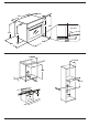
Use an appropriate cabinet to
ensure that the appliance
operates properly: to install the
oven under the counter (see
diagram) or in a kitchen unit, the
cabinet must have the
dimensions as the picture.
To ensure adequate ventilation,
the back panel of the cabinet
must be removed. It is advisable
to install the oven so that it rests
on two strips of wood, or on a
completely at surface with an
opening of at least 45 x 560 mm
as the picure.
GAS CONNECTION
WARNING: Prior to installation,
ensure that the local distribution
conditions (nature of gas and
gas pressure) and the
adjustment of the appliance are
compatible.
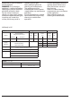
Check that the pressure of the
gas supply is consistent with the
values indicated in Table 1
(“Burner and nozzle
specications”).
WARNING: The adjustment
condictions for this appliance
are stated on the lable (or data
plate).
WARNING: This appliance is not
connected to a combustion
products evacuation device. It
shall be installed and connected
in accordance with current
installation regulations.
Particulat attention shall be
given to the relevant
requirements regarding
ventilation.
If the appliances is connected to
liquid gas, the regulation screw
must be fastned as tightly as
possible.
IMPORTANT: When gas cylinder
is adopted, the gas cylinder or
gas container must be properly
settled (vertical orientation).
WARNING: This operation must
be perfomed by a qualied
technician.
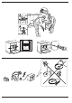
Use only exible or rigid metal
hose for gas connection.
Connection with a rigid pipe
(copper or steel)
Connection to the gas system
must be carried out in such a
way as not to place any strain of
any kind on the appliance.
There is an adjustable L-shaped
pipe tting on the appliance
supply ramp and this is tted
with a seal in order to prevent
leaks. The seal must always be
replaced after rotating the pipe
tting (the seal is provided with
the appliance).
The gas supply pipe tting is a
threaded 1/2 gas cylindrical
male attachment.
Connecting a exible jointless
stainless steel pipe to a
threaded attachment
The gas supply pipe tting is a
threaded 1/2 gas cylindrical
male attachment. These pipes
must be installed so that they
are never longer than 2000 mm
when fully extended. Once
connection has been carried
out, make sure that the exible
metal pipe does not touch any
moving parts and is not
compressed.
Only use pipes and seals that
comply with current National
regulations.
IMPORTANT: If a staineless steel
hose is used, it must be installed
so as not touch any mobile part
of the furniture (e.g.drawer). It
must pass thorugh an area
where there are no obstructions
and where it is possible to
inspect it on all its length.
The appliance should be
connected to the main gas
supply or to gas cylinder in
compliance with the current
National regulations. Before
carry out the connection, make
sure that the appliance is
compatible with the gas supply
you wish to use. If this is not the
case, follow the instructions
indicated in the paragraph
“Adapting to dierent types of
gas”.
After connection to the gas
supply, check for leaks with
soapy water. Light up the
burners and turn the knobs from
max position 1* to minimum
position 2* to check ame
stability.
ADAPTING TO DIFFERENT
TYPES OF GAS
Adapting to dierent types of
gas in order to adapt the oven to
a type of gas other than the
type for which it was
manufactured (indicated on the
label), follow these simple steps:
Replacing the oven burner
nozzle
1. Open the oven door fully.
2. Slide out the bottom of the
oven.