R-110 Whirlpool Gold 26‟ SXS 2010 Models GSF26C5EXA GSF26C5EXB GSF26C5EXS GSF26C5EXT GSF26C5EXW GSF26C5EXY GSS26C5XXA GSS26C5XXB GSS26C5XXW GSS26C5XXY Job Aid Part No.
Introduction This Job Aid, Whirlpool Gold 26‟ SXS 2010 Part Number LIT) has been compiled to provide the recent information on design, features, operation, troubleshooting and repair procedures for 26‟ SXS for 2010 . This Job Aid is not intended to replace or substitute for the Use and Care Guides or Tech Sheets associated with any of the models covered. Refer to the Technical Service sheet shipped with the refrigerator for detailed information for the unit you are servicing.
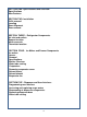
SECTION ONE- Specifications and Overview Specifications New Features SECTION TWO- Installation Grille removal Leveling Door Alignment Door removal SECTION THREE – Refrigerator Components Air inlet and outlets Damper location Water reservoir Thermistor location SECTION FOUR - Ice Maker and Freezer Components Ice maker: Access Removal Specifications Emitter/ Receiver Water tube routing Evaporator: Removing evaporator cover Defrost heater Defrost bimetal Evaporator fan SECTION FIVE - Dispenser and User Inter
SECTION SIX – Machine Compartment Components Compressor Starting components Condenser fan Water valve Control and Power supply boards Front roller Rear rollers SECTION SEVEN –Diagnostics, Wiring Diagrams and Trouble Shooting Wiring schematic Service Sheet Diagnostic routine 4
Section One Introduction Specifications and Overview 5
Safety Make sure to observe all safety warnings and messages. The Use and Care manual and Installation instructions that come with the product as well as stickers and literature attached to the refrigerator contain safety symbols. These symbols contain messages telling you of potential hazards and explain how to reduce your chance of injury. The message will also tell you what can happen if the instructions are not followed. Example taken from a Use and Care Manual.
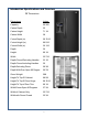
Introduction Specifications and Overview 26‟ Dimensions Dimensions Inches. Capacity 26.
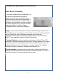
Introduction Specifications and Overview Sixth Sense Technology 6th Sense software makes an estimation of the actual food temperature inside the refrigerator and freezer compartment and adjusts cooling to allow the food packages to return their initial temperature faster during pull down, door openings, or heavy food load. 6th Sense algorithm runs in both FC and RC and each contains 3 routines: Trigger, Package Estimator, and Defrost Manager. • Trigger routine is executed every 2.
6 4 3 2 1 9 I = Inglis L = Admiral R = Roper P = Performa C = Magic Chef T = Estate W S 2 7 8 5 6 7 8 9 1 0 3 0 S 2 E X T 4 Feature Pack/Energy9 Year of Launch 3 2 – Basic E = 2008 E-Star Qualified (20%) V = 2008 W = 2009 4 – Medium R = E-Star 25% X = 2010 6 – Premium X = E-Star 30% Y = 2011 8 – Super PremiumS = E-Star 35+ A = 2012 1 Color 5 = Lowes J = E- Star 45+ 0 3 = Contract B = Black M = Meets Energy Standards A = Monochromatic Satina L = Satina Y = Monochromatic SS S = Stainless E
Section Two Installation 10
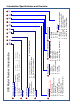
Installation This new SXS platform requires different installation steps and adjustments than current SXS refrigerators. Review the Use and Care manual and instruction sheets shipped with the product prior to installation.
Installation - Example Installation 12
Installation – Example 13
Installation Refrigerators are shipped with the handles packed in the refrigerator door. 1. Remove the handles from the door and unwrap. 1 2. The instruction sheet and a Hex key tool are attached to the handle. Review the instruction sheet. 2 3. Install the handle on the mounting studs with the hex screws facing to the center. 3 4. Hold the handle tight against the door as you tighten the screws. The handle will pull in tight against the door as the screw is tightened.
Installation Removing Grille Grille Removal The grille is held in place with 2 ¼” screws. 1. Remove screws Remove 2 ¼” screws 1 Remove grille 2. Open the doors 90 degrees perpendicular to the cabinet to remove the grille.
Installation Warning Panels – disconnect power and heavy warning Removing Freezer Door 1. Unplug or disconnect the refrigerator from the power supply. 2. Remove the screws securing the wire harnesses to the cabinet. 1 3. Disconnect water tubes form the door side of the connector 2 4. unplug the three wire harnesses plugged into the terminal board. 3 5. Remove strain relief from the wire harness. This will allow the harness to pass through the hole in the hinge.
Installation Removing Freezer Door Upper Hinge 6. Remove Two 3/16” hex key screws (A). Do not remove or loosen the other two screws (B). B A A B 5 7. Keep the door closed and lift off the hinge. Lift off the hinge 6 8. Have another person open the freezer door and lift up slowly. 7 9. As the door is lifted guide the wiring harnesses and water tubes through the hinge. 8 10. Lift the door straight up to prevent damage and kinking of the water tube.
Section Three Refrigerator Components 18
Refrigerator Compartment Light Bulbs Air Damper Air Filter 19 Water Filter
Refrigerator Compartment – cont. Disassembling Refrigerator Compartment Components Disconnect power to the refrigerator. 1. Open the water filter door and remove the filter. 1 2. Open the air filter door and remove the filter. 2 3. Remove the ¼” screw securing the air damper cover to the cabinet. 3 4. Remove the air damper cover. 4 5. Remove the ¼” screw securing the air filter housing to the cabinet and remove.
Refrigerator Compartment – cont. Disassembling Refrigerator Compartment Components – Air Damper 6. Disconnect the wiring harness and remove the air damper assembly. 6 7. Check the seal around the damper housing for any damage or misplacement. Replace or reposition seal as needed.
Refrigerator Compartment – cont. Disassembling Refrigerator Compartment Components – Water Filter Housing Remove the water filter as explained earlier. 1. Remove the ¼” screw securing the filter cover to the filter body. 1 2. Remove the cover. 2 3. Remove the ¼” screw securing the filter body to the cabinet wall. 3 4. To replace the filter housing, disconnect the water tubes in the back of the refrigerator and remove Permagum seal .
Refrigerator Compartment - cont Refrigerator Thermistor The refrigerator Thermistor is a variable resistance device connected to the control board. The temperature of the refrigerator compartment causes the resistance of the Thermistor to change. The resistance is monitored by a circuit on the control board which controls the operation of the cooling system.
Refrigerator Compartment – cont. Disassembling Refrigerator Compartment Components – Accessing Water Reservoir Remove the storage bins and shelves from the refrigerator compartment 1. The light bulb cover is very flexible and can be bent to release the 4 tabs that extend into the cabinet wall an remove. 1 2. To replace the water reservoir, Remove the ¼” hex head screw and the wire ties securing the reservoir to the cabinet. 2 3.
Section Four Freezer Compartment and Ice Maker 25
Freezer Components Freezer Thermistor The freezer Thermistor is a variable resistance device connected to the control board. The temperature of the freezer compartment causes the resistance of the Thermistor to change. The resistance is monitored by a circuit on the control board which controls the operation of the cooling system.
Freezer Components - cont Replacing Freezer Thermistor 1..Depress the tabs on either end of the Thermistor cover and remove. 1 2. To replace the Thermistor order replacement Thermistor kit through the normal part ordering system by model number. Follow the instructions supplied with the kit.
Freezer Components – cont. Warning Panel – Disconnect Power Accessing Freezer Components Unplug refrigerator and remove food and shelving. 1. Pull off the light cover located in the top left hand corner of the freezer compartment. 1 2. Remove the ¼” hex head screw below the light bulb. 2 3. Pull the top of the air duct cover out at the top and lift up to remove. 3 4. The bottom of the duct has 2 slots that slid onto the top of the evaporator cover.
Freezer Components - cont Accessing Freezer Components - Continued 5 Remove the 4 ¼” hex head screws securing the evaporator to the cabinet 5 6. Pull out the evaporator cover.
Accessing Freezer Components – Cont. Removing Evaporator Fan Motor 1. Slide out the evaporator fan motor assembly from the built in cabinet rails and disconnect the wiring harness. 1 2. To change the fan blade, pull the blade off the shaft and replace. When installing the blade, push the blade down on the shaft until it bottoms out. 2 3. Unclip the mounting bracket from the fan shroud to remove the motor.
Freezer Components –cont. Checking evaporator fan motor The evaporator fan motor is a 120 VAC shaded pole motor. To check, remove the 2 wires from the motor. Connect an Ohmmeter across the motor leads. The resistance measured should be approximately 135 Ohms plus or minus 10%. Note: the motor assembly does not have to be removed form the freezer to make this check.
Freezer Components – cont. Checking Defrost Bimetal Disconnect power to the refrigerator. 1. Slide the defrost bimetal off the coil. 2. Disconnect the wiring harness. 3. Disconnect the green chassis ground wire attached to the evaporator heat shield.
Freezer Components – cont. Replacing the defrost heater Disconnect power to the refrigerator. 1. Remove evaporator cover as explained earlier. 2. Disconnect the two black wires connected to the defrost heater. 3. Disconnect the green chassis ground wire attached to the evaporator heat shield. 4 4. Grasp the bottom of the heat shield all pull out. The heat shield is fastened to the cabinet with clips and will pull out easily. 5.
Freezer Components – cont. Freezer Door Component Location Ice Maker Ice Bin Auger Motor Compartment Drain A label on the freezer instructs the customer the Ice Maker ON/OFF switch is located behind the ice storage bin.
Freezer Components – cont. Ice Maker – Emitter /Receiver Boards The emitter board emits an infrared beam. When the eye on the receiver board sees the beam a circuit is completed indicating the ice bin is in place and not full. This signal is sent to the control board and the ice maker is energized. If the beam is not seen by the receiver board, the control board shuts off the ice maker. Emitter Receiver ON 1.
Freezer Components – cont. Accessing Ice Maker Insert Disconnect Power Warning Label 1. Disconnect power to the refrigerator. 2. Depress the ice bin latch and remove the ice bin.
Freezer Components – cont. Accessing New In Door Ice Maker 3. Remove two ¼” screws securing the housing to the inner door panel. Lift the housing up and out to remove. 3 4. When assembling insert the tabs located on the top of the housing into the slots on the inner door panel.
Freezer Components – cont. Accessing New In Door Ice Maker 5. Remove the Ice Maker wire harness cover and disconnect the harness. 5 6. Disconnect the wire harness to the emitter and receiver boards. 6 7. Remove two ¼” screws under the Ice Maker. 7 8. Slide out the Ice Maker to remove. 8 9. Remove three ¼” screws to remove housing from the ice maker mold.
Freezer Components – cont. Accessing New In Door Ice Maker Removing Ice Maker Harness 10. Unplug the wire harness from the ice maker head. 10 11. Slide off the Hi Limit control from the mold.
Freezer Components – cont. Ice Maker New Six Cavity Ice Maker Component Identification Bracket Head Ice Stripper Ejector Blade Module Mold Components Disassembling the Ice Maker. N M 1. Remove the ice maker cover. A module similar to the existing product is used. The module is checked exactly as the current module. Jumping “T” to “H” will begin a harvest cycle.
Freezer Components – cont. Disassembling the Ice Maker –Module Removal 2. Remove three screws that secure the module to the head. 2 Separating IM Head From the Mold 3. Separate the module from the head 3 4. Remove two screws on the bottom of the ice maker head and separate the head from the mold. The Thermostat can be removed at this point. 4 5. When replacing the thermostat apply a coating of Alumilastic to the mold . This will provide a thermal bond between the mold and thermostat.
Freezer Components – cont. Replacing Auger Motor and Related Components 1. Remove two screws and lift off cover. 1 Coupling 2. Remove the coupling by lifting straight up. A spring is captured under the coupling. Spring 2 3. To access the motor remove the four ¼” screws securing the chute to the housing. 3 4. Lift out the chute. The chute may require some effort to remove because of the foam seal around the chute tube. 4 5. Inspect seal and repair and replace if necessary before reassembly.
Freezer Components – cont. Removing Auger Motor 6. Remove four ¼” screws securing the motor to the housing . 6 7. Lift up the auger motor and disconnect the wire harness. 7 Condensate Drain Under normal operating conditions, moisture may accumulate in the bottom of the auger motor housing. A drain hole is provided to allow water to pass through the inner door panel and drop onto the lower shelf, see figure 2.
Freezer Components – cont. Checking the Auger Motor Connect an Ohmmeter across the two motor terminals and measure the resistance. The resistance should be approximately 210 Ohms plus or minus 10%. Removing Emitter and Receiver Boards Release 4 tabs to remove the emitter and receiver boards from the housing.
Water Tube Routing Water Routing: the home water supply is connected to the isolation valve. The outlet of the isolation valve connects to the water filter located in the refrigeration compartment. The outlet of the filter connects to the inlet of the water reservoir. The water reservoir outlet connects to the inlet of the dual valve. Freezer Door The ice maker fill tube and the water dispenser tube are routed through the hole in the lower freezer door hinge.
Section Five Dispenser and User Interface 46
Programming Stealth Control Amber Red Figure 1 – Whirlpool Stealth User Interface/Blue LED‟s except as noted. The Icons used on this Whirlpool user interface display are similar to those used on other SXS models but not identical. The basic operation and programming is the same. .
Recommended Setting Order Filter Refrigerator Refrigerator Cooling is Off Freezer Back ICE MODE Units Select Zone LIGHT TEMPERATURE Hold 3 Sec. MAX ICE Replace Filter + LOCK Hold 3 Sec. Confirm RESET FILTER Hold 3 Sec. Figure 3 – KitchenAid Interface Icon Identification Figure 3 depicts all the ICONS and Text located on the Display. Specific Icons will be displayed at different steps during programming as explained in this manual. .
ICE MODE LIGHT TEMPERATURE Hold 3 Sec. MAX ICE LOCK Hold 3 Sec. RESET FILTER Hold 3 Sec. Figure 5 Pressing any control button will activate the “Normal/Home ” display screen, without changing any settings. See figure 5. After activation, changes to any settings can then be made. If no changes are made within 2 minutes, the display will re-enter “sleep” mode. Factory Preset Temperatures The refrigerator and freezer controls are preset at the factory.
Recommended Setting Refrigerator Back ICE MODE Units Select Zone LIGHT TEMPERATURE Hold 3 Sec. MAX ICE + LOCK Hold 3 Sec. RESET FILTER Hold 3 Sec. Figure 7 Adjusting Temperature Set Points: Pressing and holding TEMPERATURE starts a 3,2,1 second countdown. During the countdown using the dispenser cancels the countdown and no dispensing is permitted. The number „3‟ blinks 3 times and an „invalid‟ tone sounds 3 times,.
Recommended Setting Refrigerator Lower Back ICE MODE Units Select Zone LIGHT TEMPERATURE Hold 3 Sec. - Raise + MAX ICE Confirm LOCK Hold 3 Sec. RESET FILTER Hold 3 Sec. Figure 8 Adjusting Temperature Settings Press the LOCK pad to raise the temperature set point or press the MAX ICE pad to lower the temperature set point. See figure 8.
ICE MODE LIGHT TEMPERATURE Hold 3 Sec. MAX ICE LOCK Hold 3 Sec. RESET FILTER Hold 3 Sec. Figure 10 Ice Dispenser: Ice dispenses from the ice maker storage bin in the freezer when the dispenser lever is pressed. The ice maker can produce both crushed and cubed ice. Before dispensing ice, select which type of ice you prefer by pressing the ICE MODE button. The display screen indicates which type of ice is selected. See figure 10. For crushed ice, cubes are crushed before being dispensed.
ICE MODE LIGHT TEMPERATURE Hold 3 Sec. MAX ICE LOCK Hold 3 Sec. RESET FILTER Hold 3 Sec. Figure 11 Max Ice: The Max Ice feature assists with temporary periods of heavy ice use by increasing ice production over a 24-hour period. IMPORTANT: This feature only works if the ice maker is turned on. Press MAX ICE to turn on the Max Ice feature. When the feature is on, the Max Ice icon will appear on the dispenser display screen. See figure 11.
ICE MODE LIGHT TEMPERATURE Hold 3 Sec. MAX ICE LOCK Hold 3 Sec. RESET FILTER Hold 3 Sec. Figure 12 Dispenser Light: When you use the dispenser, the light will automatically turn on. If you want the light to be on continuously, you may choose either ON or DIM. The display screen indicates which mode is selected. See figure 12. ON: Press LIGHT to turn the dispenser light on at 100% DIM: Press LIGHT a second time to select DIM mode. The dispenser light will remain on, but at a lower 50% intensity.
Door Open Icon ICE MODE LIGHT TEMPERATURE Hold 3 Sec. MAX ICE LOCK Hold 3 Sec. RESET FILTER Hold 3 Sec. Figure 13 Door Open Alarm The Door Ajar Alarm feature sounds an alarm when the refrigerator or freezer door is open for 5 minutes and the product cooling is turned on. The alarm will repeat every 2 minutes. Close both doors to turn it off. The feature then resets and will reactivate when either door is left open again for 5 minutes.
ICE MODE LIGHT TEMPERATURE Hold 3 Sec. MAX ICE LOCK Hold 3 Sec. RESET FILTER Hold 3 Sec. Figure 14 Dispenser Lock: The dispenser can be turned off for easy cleaning or to avoid unintentional dispensing by small children and pets. NOTE: The lock feature does not shut off power to the refrigerator, to the ice maker, or to the dispenser light. It simply deactivates the controls and dispenser levers. Details Pressing and holding LOCK starts a 3,2,1 second countdown.
Cooling is Off ICE MODE LIGHT TEMPERATURE Hold 3 Sec. MAX ICE LOCK Hold 3 Sec. RESET FILTER Hold 3 Sec. Figure 15 Cooling Off Mode Pressing and holding both LOCK and RESET FILTER simultaneously, see figure 15, starts a 3, 2, 1 second countdown. During the countdown, using the dispenser cancels the countdown AND no dispensing is permitted. After 3 seconds, the „cooling off‟ icon appears and flashes 7 times then remains on. All the rest of the icons including door ajar turn off.
Order Replace ICE MODE LIGHT TEMPERATURE Hold 3 Sec. MAX ICE LOCK Hold 3 Sec. RESET FILTER Hold 3 Sec. Figure 16 Water Filter Status Light: The water filter status light will help you know when to change your water filter. When the dispenser control panel‟s water filter status display changes to “ORDER,” this tells you that it is almost time to change the water filter cartridge. Replace the water filter cartridge when the water filter status display changes to “REPLACE.
ICE MODE LIGHT TEMPERATURE Hold 3 Sec. MAX ICE LOCK Hold 3 Sec. RESET FILTER Hold 3 Sec. Figure 17 Showroom Mode: Pressing and holding LIGHT and MAX ICE starts a 3,2,1 second countdown. During the countdown, pressing any other button or releasing a pad cancels the countdown. Details: After 3 seconds, the control enters the showroom mode and the cooling system turns off.
Dispenser Components Accessing User Interface and Dispenser Components Insert Disconnect Power Warning Label 1. Disconnect power to the refrigerator 2. Remove the and the 2 Location of tabs 3. Release three locking tabs securing the User Interface to the dispenser housing.
Dispenser Components Accessing User Interface and Dispenser Components 4. Drop down the User Interface board 4 5. Remove the wire harnesses 5 6. Remove the four screws securing the dispenser housing to the door panel. 6 7. Disconnect the water tube from the dispenser assembly.
Dispenser Components Accessing User Interface and Dispenser Components 8. Remove two ¼” hex head screws securing the dispenser assembly to the door panel. 8 9. Remove the wiring harnesses from the dispenser bracket Remove the wire harnesses. 9 Left Clip 10. Release the retaining clips on the left and right side of the dispenser. Right Clip 10 11. Pull the top of the dispenser housing out about 2” to allow removal of the dispenser assembly. 11 12. Remove two screws to replace the dispenser motor.
Dispenser Components Accessing User Interface and Dispenser Components 13 13. The dispenser door can be snapped out t to replace. Note: The door can be replaced without removing the assembly. Depress Here 14. To replace a switch, depress the release in the center slot and slide off the switch.
Section Six Machine Compartment 64
Machine Compartment & Control Boards Gum Seal Wrapped Around Water Tubes Water Tubes to Water Filter.
Machine Compartment Components Insert Disconnect Power Warning Label Accessing Components 1. Disconnect power to the refrigerator‟ 2. Remove the ¼” screws securing the fiber cover to the cabinet. 2 3. To remove the start module remove the bail and unplug the module. 3 4. Unplug the wire harness. 4 5. The run capacitor unplugs from the module.
Machine Compartment Components Starting Device Operation The starting device is an assembly consisting of an overload (1) and a PTC relay (2). The PTC relay is composed of a semi conductive substance formed in the shape of a disk (2). The disk is connected in series with the run and start terminals which in turn connect to the run and start windings. The resistance of the disk material is relatively low at room temperature.
Machine Compartment Components Accessing Dual Water Valve: The valve is located in the machine compartment attached to the compartment wall. To Remove: 1. Disconnect the refrigerator from the power supply. 2. Unsnap the water valve assembly out of the bracket. 2 3.
Machine Compartment Components Condenser Fan: The condenser fan motor is a step motor and cannot be checked with an Ohmmeter. The condenser fan blade can be pulled off to replace without removing the assembly. Wire Harness To remove the condenser fan motor: 1. Disconnect power to the refrigerator. 2. Pull off the fan blade 3. Disconnect the wire harness. 4. Remove the screws securing the motor to the mounting bracket and remove motor. Screws To remove the condenser fan assembly: 1.
Machine Compartment - Drain Pan The drain pan is much larger than anything that has been used recently. It‟s secured to the bottom of the cabinet with five ¼” screws.
Machine Compartment - Front Roller A center roller assembly replaces the tradition corner wheel design used on other n models. Axle The axle is held in place by a locking clip. The refrigerator must be tilted back to remove. Locking clip To remove the roller: 1. Elevate the front of the refrigerator a few inches so the wheel is off the floor. Clip 2. Remove the axle clip and slide out the axle. 2 3. Remove the axle and wheels.
Accessing the Control and Power Supply Board. Control and Power Supply Boards Similar to existing refrigerators, the control and power supply boards are located behind a cover on the back of the refrigerator. To access the boards: 1. Disconnect the refrigerator from the power supply. 2. Remove four ¼” screws securing the cover to the cabinet. 2 3. Remove the clear cover by unsnapping the latch on the right hand side of the cover. 3 Control Board 4. To change a board, disconnect wiring harnesses. 5.
Section Seven Diagnostics, Wiring Diagrams and Troubleshooting 73
Diagnostics, Wiring Diagrams and Troubleshooting 74
Diagnostics, Wiring Diagrams and Troubleshooting 75
Diagnostics, Wiring Diagrams and Troubleshooting Insert Warning Label 76
Wiring Diagrams and Troubleshooting Temp F Resistance -10 31402 -5 26704 0 22774 5 19476 10 16701 15 14359 20 12378 25 10698 30 9268 40 7007 45 6115 Temp F Resistance 50 5348 55 4687 60 4117 65 3624 70 3197 75 2826 80 2503 85 2221 90 1974 95 1758 100 1569 Thermistor Resistance Table 77
Diagnostics, Wiring Diagrams and Troubleshooting 79