
Instruction for Use


4
GB
PLEASE PHONE US TO REGISTER YOUR APPLIANCE AND ACTIVATE YOUR PARTS GUARANTEE ON 08448 24 24 24
Installation
WARNING - THIS APPLIANCE MUST BE
EARTHED.
Mains Connection
Your cooker should have been checked to ensure that
the voltage corresponds with your supply voltage, this is
stated on the rating plate, which is situated on the outer
rear panel.
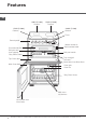
The model number and serial number are located on
the front of the cooker, as shown on the Feature’s page.
The cooker must be connected by a competent person
such as one who is a, NICEIC registered contractor
to a suitable double-pole control unit with a minimum
rating of 32A and a minimum contact clearance of 3mm
(applicable to newer properties, older properties where
a 30A double pole control unit and a minimum contact
clearance of 3mm is acceptable).
The double pole control unit should be fitted adjacent
to the cooker, in accordance with IEE regulations. The
control unit must be within 2 metres of but not directly
above the appliance and should be easily accessible in
the event of an emergency.
The power supply cable should conform to B.S.6004 with
a conductor size of 6mm2, minimum.
Access to the mains terminals is gained by removing the
rear access cover. The mains cable must pass through
the cable clamp adjacent to the terminal block. Sufficient
cable should be used to allow the cooker to be pulled
out for servicing.
Ensure that the mains cable is routed away from any
brackets affixed to the rear panel and is not trapped
to the rear wall when pushing the cooker into position
between cabinets.
Levelling
Four feet are fitted which can be adjusted up or down to
set the height (900mm - 930mm) and level the cooker.
The feet can be simply screwed in or out to lower or raise
the cooker.
After the correct height is achieved, lock the feet into
position by tightening the locking nut using an open
ended spanner.
CAUTION: Some soft floor coverings may get damaged
if the cooker is not moved carefully.
NOTE: Ensure oven shelves are level by using a spirit
level on the rod shelves.
Siting the Cooker
The cooker is designed to fit between kitchen cabinets
spaced 600mm apart. The space either side need only be
sufficient to allow withdrawal of the cooker for servicing
and cleaning.
It can be used with cabinets one side or both as well
as in an angled corner setting. It can also be used
freestanding.
Adjacent side walls which project above hob level, must
not be nearer to the cooker than 150mm and should be
protected by heat resistant material. Any overhanging
surface or cooker hood should not be nearer than 650mm.
Note: This appliance must NOT be fitted on a platform.
Moving the Cooker
Before moving your cooker, switch off at the cooker
control unit, ensure that it is cool.
Open the grill door sufficiently to allow a comfortable grip
on the underside front edge of the oven roof, avoiding
any grill elements.
Radio Interference
This appliance conforms to EN 55014 regarding
suppression of radio and television interference.
Note: Take care in moving the cooker as it is heavy.
Take care to ensure that any floor covering is not
damaged.
Technical Characteristics
Top Oven
Usable Volume: 39 Litres
Declared energy consumption for
Natural convection Class
heating mode: Conventional
Main Oven
Usable Volume: 71 Litres
Declared energy consumption for
Forced convection Class
heating mode: Fan Oven
Voltage and Frequency
230-240V~ 50Hz
ENERGY LABEL and ECODESIGN - Top Oven
Regulation (EU) No 65/2014 supplemen-
ting Directive 2010/30/EU.
Regulation (EU) No 66/2014 implementing
Directive 2009/125/EC.
Standard EN 60350-1
Standard EN 50564.
ENERGY LABEL and ECODESIGN - Main Oven
Regulation (EU) No 65/2014 supplemen-
ting Directive 2010/30/EU.
Regulation (EU) No 66/2014 implementing
Directive 2009/125/EC.
Standard EN 60350-1
Standard EN 50564.
HobHobHob
ECODESIGN
Regulation (EU) No 66/2014 implementing
Directive 2009/125/EC.
Standard EN 60350-2.
Standard EN 50564.
The appliance must not be installed behind
a decorative door in order to avoid overheating
The appliance must not be installed behind
a decorative door in order to avoid overheating
After installing the power cable, screw the metal cover
with three screws.