Service & Installation manual Light programmable oven with boiler
Table of Contents Preface and terms of warranty Rating plate Installation and connection -Installation -Water connection -Drain connection -Electrical connection/survey of supply lines Exhaust Checking before use Annual service check Start menu Oven set-up -Set-up mode U1 to U9 -Set-up mode U10 to U15 Test functions -Test mode D0 to D6 -Test mode D7 to D15 -Test mode D16 to D20 -Test mode D21 to D28 -Test mode D29 to D47 User menu -User menu B1 to B6 -User menu B7 to B12 -User menu B13 to B20 -User menu B2
Preface and Terms of Warranty You are now the owner of one of the leading oven products on the market. All WHIRLPOOL products are currently subjected to intensive product development, which ensures that the products always contain the latest technology and the most up-to-date and energy-saving methods of preparation.
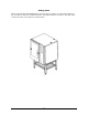
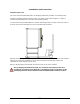
Rating Plate When communicating with WHIRLPOOL, we kindly ask you inform us of the serial number of the oven that is stated on the approval plate. The approval plate is located on the right-hand corner post of the oven cabinet, as shown below.
Installation and Connection Unpacking the oven The oven is best handled while still in its wrapping. Wherever possible, use a lifting trolley. Introduce the lifting trolley under the lower cross tube of the stand and place a couple of wooden blocks between the cross tube and the lifting trolley. To achieve the best possible balance, introduce the lifting trolley from the front of the oven or from the motor side. Note that the oven can be lifted off the stand. Remove the original packaging from the oven.
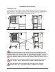
Installation and Connection Installing the oven To ensure that the oven functions correctly when installed, it should be placed upright and level (horizontally). This is measured at the front and side edge of the roof, and adjustment is made by means of the adjusting screws on the stand or on the legs of table models. The height of the oven can also be adjusted to fit the trolley for rack.
Installation and Connection Water connection WHIRLPOOL ovens have one or two water connections. To facilitate cleaning and service, the oven should be connected with an approved flexible ¾’’ hose and the permanent installations should be fitted with a stop tap. Before connecting the oven to water, flush the tubes thoroughly. Hardness of the water: Conductivity: Water pressure: max. 3 dH min. 75 microsiemens min. 2.5 bar (36 PSI) dynamic pressure (when CombiWash on), max. 6 bar (87 PSI) Water flow: min.
Installation and Connection Drain connection From the factory, the WHIRLPOOL ovens are equipped with a drain system that removes surplus water from the oven chamber. This water may be condensed water from the products, or it may occur when the oven chamber is cooled down with cold water, or when the oven chamber is cleaned. Connection must be carried out by an authorised plumber, to an open or to a closed drain.
Installation and Connection Electrical connection/survey of supply lines The electrical connection must be carried out by an authorised electrician in accordance with existing rules and regulations. The wiring diagram is located in the motor compartment. The terminal for the electrical connection is located behind the right side plate. An approved plug outlet or a safety cutout must be located close to the oven so that the oven can be disconnected during installation and repair.
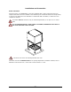
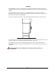
Exhaust The WHIRLPOOL ovens are equipped with an open/direct exhaust system that removes surplus humidity from the oven chamber. The exhaust system has an electrically operated damper. The exhaust tube can be connected to a ventilating system. In that case, a special extraction funnel is fitted to avoid suction directly from the oven chamber. This extraction funnel can be ordered from WHIRLPOOL. The scope of supply also includes a specially designed extraction hood, see illus. below.
Checking before Use The oven should be checked before you start using it. On the outside • • • Check that the oven has not been damaged in transit (dents, scratches, etc.
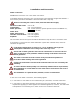
Annual Service Check Customer: Address: By: Postal code: Serial No of the oven: Model: 1. Connection: Functioning correctly Water connection – dirt filter (may need tightening) Electrical connection (may need tightening) Drain connection (may need tightening) Positioning of oven 2. Door: Closing device (may need adjusting) Catch (may need adjusting) Sealing (must be tight at 100°C steam or combi steam) Hinging (may need adjusting) Interior glass (hinging, fastening) Calibrate door sensor 3.
6. Steam generator: Heating elements (check for leaks) Load distribution on phases Level sensor – to be cleaned Drain pump May need descaling Functioning correctly YES NO 7. Functional test: Components (use test function) Core temperature probe Operation modes CombiWash (clean jet head) Service engineer: Date and signature Parts to be replaced at 12-, 24- and 36-month service intervals: 12-month inspection Follow the annual service check (see above).
Start Menu Main switch Change oven temperature with turn switch HOT AIR selected if control lamp on COMBI STEAMING selected if upper or middle control lamp is on. REHEATING is selected if lower control lamp is on. Change time with turn switch Core temperature on C and K models. Injection time on B model. Steaming on C and K, preheating on B Program key Exhaust open if control lamp on Step key Fan speed can be set between 20 and 100%. Control lamp is on when speed < 100.
Oven set-up Main switch Display shows setting Press HOT AIR and STEAMING for 2 sec. Not active Possible to change to "d" test mode with combi steam key Display shows "U" No. Press STEAMING/ PREHEATING and HOT AIR for 2 sec. Display shows description of "U" function Not active Display shows setting Not active Confirmation of special settings Select "U" settings with turn switch Not active To enter set-up mode, press hot-air key and steaming/preheating key for 2 sec.
Set-up Mode U In the set-up function, it is possible to set the oven controller to match the mechanical set-up and the choice of software. If the set-up has been changed in U1, U4 or U15, the oven will be reset. U1 Oven model The setting should be set to 1( by pressing the step key ). You press the temperature key to select a PassThrough model (two doors). 1= one door (standard) 2= two doors When you have selected the oven model, confirm by pressing the alarm key if the control lamp flashes.
0= OFF, 1= 10 programs with 3 process steps. NOTE: It is still possible to activate the cleaning program even though the program mode is not active. 0= OFF. U11 Core temperature probe You activate and deactivate the core temperature probe by pressing the step key. 0= OFF, 1= ON. U12 Drain cooling You activate and deactivate drain cooling by pressing the step key. 0= OFF, 1= ON. U13 Timer start You activate or deactivate timer start by pressing the step key. 0= OFF, 1= ON.
Test Mode Main switch Display shows setting For test mode, press HOT AIR and COMBI STEAMING for 2 sec. Display shows setting For test mode, press COMBI STEAMING and HOT AIR for 2 sec. Display shows "d" No.
Test Mode D0-D6 In the test mode, it is possible to activate all electrical components. This is very useful in connection with fault detection and the testing and adjusting of replacement parts. D0 Main contactor(s) This function activates contactor K1. You activate or deactivate the function by pressing the step key. The function can, however, only be activated when the fan is on. To pulse, press the alarm key. 0= OFF, 1= ON.
Test Mode D7-D15 D7 Filling valve This function activates solenoid valve MV2. You activate or deactivate the function by pressing the step key. To pulse, press the alarm key. 0= OFF, 1= ON. D8 Drain pump This function activates motor M2. You activate or deactivate the function by pressing the step key. To pulse, press the alarm key. 0= OFF, 1= ON. D9 Drain cooling This function activates solenoid valve MV3. You activate or deactivate the function by pressing the step key. To pulse, press the alarm key.
Test Mode D16-D20 D16 Core temperature This function is not available on B models. C and K models can use only one core temperature probe, it is possible, however, to test core temperature probes 1 and 2. Here it is possible to read the current temperature of the core temperature sensor, P2 + P2A. In the field next to ”Temperature”, the current temperature is shown. If ERR appears, the sensor circuit is defective. In the field next to ”Time”, an adjustment value between 80 and 120 (default 100) is shown.
Test Functions D21-28 D21 Water level Here it is possible to read the status of SE2. In the display next to ”Time”, the conductivity is shown and it is indicated whether the water level is high or low XX|LO= low water level, XX|HI= high water level. XX = conductivity of the water. Default setting is approx. 80 with no water and 40.60 with water. The better the conductivity, the lower the measured value. D22 Thermo-switch oven Here it is possible to read the status of Q1 and Q1A.
Test Mode D29-D47 D29 CombiWash water Only possible on ovens with CombiWash. This function activates solenoid valve MV4. You activate or deactivate the function by pressing the step key. To pulse, press the alarm key. 0= OFF, 1= ON. D34 Water pressure sensor Here it is possible to read the status of P7. OF|HI= water pressure adequate, ON|LO= water pressure inadequate.
User Menu Main switch Display shows setting Not active Display shows setting Not active Display shows "b" No. Not active Display shows description of "b" function Not active Display shows setting Not active Press key for 5 sec. to access user menu Turn switch Start/Stop To enter user menu, press alarm key for 5 sec. To exit user menu, turn the switch to the left. The user menu can be operated by the end-customer as well as by the service engineer.
User Menu B1-B7 B1 Save presettings In this function, you save the preset time and temperature. If, for instance, the end user uses HOT AIR at 180°C for 30 minutes, the standard setting can be changed as follows: 1. 2. 3. 4. Change time and temperature. Enter user menu (keep pressing alarm key for 5 sec.) Select B1 (save presettings). Press alarm key to accept. You can only save the settings when the control lamp next to the alarm key flashes.
User Menu B8-B13 B8 Exhaust In this function, you choose whether the oven should start up the extraction hood. 0= Extraction hood not controlled by oven 1= Extraction hood runs for 10 minutes after oven has stopped. This applies to an extraction hood mounted on the oven as well as for an external extraction hood. B9 Time graphics In this function, you determine whether the oven should be able to show graphically how long time has passed of a cooking sequence. You choose between 0 and 1.
User Menu B14-B21 B14 year In this function, you set the year. 1. Press the key next to the temperature display (digit flashes). 2. Turn the switch to the desired setting. 3. Press the key next to the temperature display (digit stops flashing). You set the year from 6 to 20. B15 CombiWash In this function, you activate or deactivate CombiWash. 0= Manual cleaning 1= CombiWash Press step key to change setting. B16 Pulsing interval, reheating In this function, you set the pulsing time in the reheating mode. 1.
User Menu B22-B24 B22 Screen saver In this function, you set the time that should pass until the clock appears in the display. Press step key to select time. 0= no screen saver 1= 10 sec. 2= 30 sec. 3= 60 sec. 4= 180 sec. 5= 600 sec. The screen saver appears when the oven has been idle for a particular period of time. B23 Language In this function, you change the language of the computer. Press step key and select 1 to 9. There are two language variants: A – B (see below).
Error codes Main switch Display shows error "Er" No Display shows description of error Turn switch Start/Stop All keys can be used to acknowledge an error message.
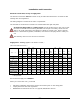
Error codes Error code 3: GENRA HOT Error code 4: OVEN HOT Error code 5: FAN HOT Error code 6: DRAIN > 75 Error code 7: OVEN SENS Error code 8: PROBE SENS Error code 9: GENER SENS Error code 10: DRAIN SENS Error code 11: WATER SHOR Error code 12: SSR HOT Error code 13: GENER > 130 Error Error Error Error Error FAN SPEED CPU HOT IO BRD HOT DATA ERROR WRONG LANG code code code code code 14: 15: 16: 18: 19: Error code 20: NO COM IO Error code 22: Error code 23: NO RESTART OVEN WAR
Appendix No 1 WHIRLPOOL INSTALLATION CHECKLIST FOR VISUAL COOKING OVENS To be filled out at each installation of a WHIRLPOOL oven. In order for the oven to qualify for warranty, this check list must be filled out by the service engineer installing the oven and returned to WHIRLPOOL within 30 days of the date of installation. Serial no.
Access to the oven: Recommended distance for service and for installation near other heatgenerating appliances (all oven sizes). All ovens Left side minimum Rear side minimum 50 mm (2”) 50 mm (2”) Right side minimum 400 mm (15”) Distance measured in mm Drain connection: Yes No Yes No Yes No Heat-resistant drain tube connected. Fall of at least 3º or 5%. CombiPlus fitted with open drain for both ovens. The drain must never end directly under the oven.
Appendix No 2 WHIRLPOOL INSTRUCTION CHECKLIST FOR VISUAL COOKING OVENS To be filled out for each installation of a WHIRLPOOL oven. In order for the oven to be qualified for warranty, this check list must be filled out and returned to WHIRLPOOL within 30 days of the date of instruction.
Notes: _________________________________________________________________________ _________________________________________________________________________ _________________________________________________________________________ _________________________________________________________________________ _________________________________________________________________________ _________________________________________________________________________ _____________________________________________________________
Notes: _________________________________________________________________________ _________________________________________________________________________ _________________________________________________________________________ _________________________________________________________________________ _________________________________________________________________________ _________________________________________________________________________ _____________________________________________________________