
Installation manual

- 9 -
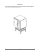
Installation and Connection
Electrical connection/survey of supply lines
The electrical connection must be carried out by an authorised electrician in accordance with
existing rules and regulations.
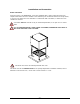
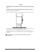
The wiring diagram is located in the motor compartment.
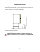
The terminal for the electrical connection is located behind the right side plate.
An approved plug outlet or a safety cutout must be located close to the oven so that
the oven can be disconnected during installation and repair. The safety cutout must be
able to cut off all poles with a total distance of break of at least 3 mm. Each of the two
units in a stacked arrangement (CombiPlus) must have its own plug outlet or safety cut-
out.
The warranty does not cover incorrect connection.
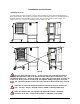
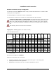
Supply lines - survey (applies to all electric models )
(All cross sections in mm² )
382,
395
382,
395
AFO ----Æ
375,
388
375,
388
376,
377,
378,
389,
390,
391
376,
377,
378,
389,
390,
391
379,
392
379,
392
380,
393
380,
393
383,
396
383,
396
384,
397
384,
397
9 kW Fuse 18 kW Fuse 24 kW Fuse 36 kW Fuse 27 kW Fuse 60 kW Fuse
400V 3N ~ 50/60
Hz
5x2,5 16A 5x4 35A 5x10 50A 5x10 63A 5x10 50A 5x25 100A
400V 3 ~ 50/60
Hz
4x2,5 16A 4x4 35A 4x10 50A 4x10 63A 4x10 50A * *
415V 3N ~ 50/60
Hz
5x2,5 16A 5x4 25A 5x10 50A 5x10 50A 5x10 50A 5x25 100A
440V 3 ~ 50/60
Hz
4x2,5 16A 4x4 25A 4x10 50A 4x10 50A 4x6 35A * *
200V 3 ~ 50/60
Hz
4x4 35A 4x16 63A 4x25 100A 4x35 125A 4x25 80A * *
230V 3 ~ 50/60
Hz
4x4 25A 4x10 50A 4x25 80A 4x35 100A 4x25 80A * *
480V 3 ~ 50/60
Hz
4x2,5 16A 4x4 25A 4x6 35A 4x10 50A 4x6 35A * *
208V 3 ~ 50/60
Hz
4x4 25A 4x10 50A 4x25 80A 4x35 100A 4x25 80A * *
* Not possible
Recommended supply line: H07RN-F
When you connect the oven, you should
• Follow the installation instructions and the information given on the rating plate.
• Comply with local rules and regulations.
• WHIRLPOOL recommends the use of a (Type B) RCD/RCCB. 300 mA