
Service manual

-.
When local
When local
codes.. . codes.. .
Alternate
electrical
connection
Electrical Shock
Hazard
A
.
B .
Permit use of a flexible type power
supply cord (pigtail) that comes
equipped with the washer/dryer but
Do Not Permit connecting the
cabinet-grounding conductor to
the neutral wire of the power supply
cord:
cenlsr sllvercolorad
Groundi
“R,
we
lermlnal tick screw
(green WI
and neuhal
Y.IIOW ShlPeer)
Do Not Permit the use of the flexible
power supply cord equipped with
the washer/dryer and
Permit solid copper power supply
cable and
Permit connecting cabinet-
grounding conductor to the neutral
wire of the power supply cable:
. Electrical ground is required on
this appliance.
. Improper conneclion of the
equipment-grounding
conductor line con result in
electrical shock.
. Check with a auakfied
eleclrician if ydu are in doubt
OS to whether Ihe appliance is
properly grounded.
- Do NoI modlly the power
supply cord plug. If it will not fit
the outlet, have a proper outlet
installed by a aualilied
electrician.
. Use Q new 30-ampere power
supply cord kit. Do Not reuse on
old Dower SUDDIY cord. Possible
electrical shdckgr Rre hazard
could occur It old power supply
cord is used.
. Disconnect the power supply
cord from Ihe electric supply
before making these changes.
Failure to do so may result in
personal injury.
Failure to follows these
inslructions could result
in
electrical shock.
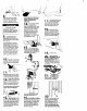
Figure 4
1. Disconnect the power
supply.
2. Remove the power cord
equipped with the washer/dryer as
instructed. See ‘To remove the
power supply cord’. Panel F.
3. Install solid copper, power-supply
cable through strain relief.
4. Connect the neutral wire of the
flexible armored or non-metallic
sheathed, solid copper power-
SUDDIV cable to the center. silver-
cdl&d terminal screw and the
terminal block. Connect the other
wires to the outer teninals. Tighten
screws firmlv See Fiaure 4. For
plain-end wires. see:Dlrect wlrlng
connection.’ Pcnel F.
5. Replace the terminal block cover,
Figure 3
1. Disconnect the power supply.
2. Remove terminal block cover.
3. Remove the grounding wire
(green with yellow stripes) from
the external grounding
connector and fasten under
center, silver-colored terminal
block screw. See Figure 3.
4. Connect a separate copper
aroundina wire (NO. IO minimum).
See “To c‘bnnect a separate
.
grounding wire-, Panel F for
detailed instructions.
5. Replace the terminal block
cover.
This appliance is manufactured with
the neutral terminal connected to
the cabinet.
To connect a separate
grounding wire -
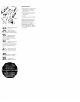
po;;move the power supply
1. Disconnect the power supply
2. Remove the terminal block cover
from the dryer.
3. Disconnect the power supply cord
from the termlnol block.
4. Use a screwdriver to loosen the
strain-relief screws.
5. Pull downword on the power
supply cord until it is removed from
the dryer. See Figure 9.
Direct wiring connectton
1, Strip the outer covering back 3
inches from the end exposing the
three wires.
2. Strip the lnsulatlon back 1 Inch
from the end of each wire. Form
the bare wires into a V-shaped
hook. See Figure 10.
P p pe
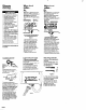
Use grounding wire and clamp
assembly (Part No. 685463) or No.
IC-gauge minimum copper
grounding wire.
No. A
who
Cold
waler
Pblnw7d wlflng
Figure IO
3. Loosen, do not remove, screws
from terminal block. Attach wires
according to instructions for type
of connection needed,
4. Slide the end of each wire
under the screw head with the
open side of the screw hook on
the right. Squeeze the wire
._
rogerner To rorm a loop.
5. Tlghten each screw firmly.
6. Tighten strain relief screws
I:
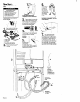
Figure 8
Connect grounding wire to
a grounded cold-water pipe’ with
the clamo and then to the external
grounding connector on the
washer/dryer. (See Figure 3.) Do not
ground to a gas supply pipe or hol-
water pipe. Do not connect the
power supply cord to electric
power supply until the appliance
is permanently grounded.
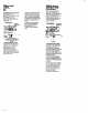
‘Grounded cold-water pi
e mut have
metol continuify to &c+rcaf ground and
P
not be interrupted by
lztlc. rubber of
0rnel
e~~hicaf 1~10
tP ng connecton
such OS tlorEs.
ntthgs.
washer or gaskets
(Includl”~ water meter a pump). A,,”
eleCtrIca
ImulaHn comector shtid be
lumped as shown
a
Ffgwe 7
tim 0 lengm
Of NO. 4 tire securely Clamped to bale
metal at both ends.
Panel F