
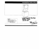
Service manual

When local
codes.. .
C
.
Do Not Permit the use of the flexible
power SUODIV cord eauiooed with
the wash&/dryer and’
Permti copper, power-supply cable
and
Do Not Pen-nit connecting
cabinet-grounding conductor to
the neutral wire of the power
supply cable:
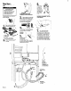
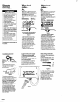
Figure 5
1. Disconnect the power supply.
2. Remove the power supply cord
equipped with the washer/dryer as
instructed. See “To remove the
power supply cord’. Panel F.
3. lnstoll copper, power-supply
cable through strain relief.
4. Remove the grounding wire
(green with yellow stripes) from the
external aroundina connector and
fasten under cent&. silver-colored
terminal block screw.
5. Connect the neutral wire of the
flexible armored or non-metallic
sheathed. copper power-supply
cable to the center, sihrer-colored
terminal screw of the termlnal
block. Connect the other wires to
the outer terminals. Tighten screws
See Figure 5. For plain-end wires,
see ‘Direct wiring connection.’
Panel F.
6. Connect a separate copper
grounding wlre (NO. 10 minimum).
See ‘To connect a separate
grounding wire’, Panel F, for
detailed Instructions
7. Replace the terminal block
cover.
-.
Mobile home
and four-wire
installation
When a four-wire receptacle,
NEMA Type 14-3OR is used. a
matching 120/240 volt minimum,
JOampere. U.L.-llsted dryer power
supply cord kit(pigtai0 must be
used. This cord contains four, No. 10
copper conductors with ring
terminals or spade terrnlnals with
upturned ends on dryer end
terminating In a NEMA Tvpe 14-30P
plug on supply end.
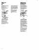
Groundlng
WI. (green With
1. Disconnect the power supply.
2. Remove the power supph/ cord
Figure 6
equipped with the washer/dryer
as instructed. See Panel F. ‘To
remove the power supply cord’.
3. Install copper, 4-wlre power
SUDDIV cord or cable throuah strain
reiief.‘Trghten strain relief sc;ews.
4. Remove the grounding wire
(green with yellow stripes) from the
external grounding connector and
fasten under center. sitver-colored
terminal block screw.
5. Connect the aroundina wire
(green with vell6w strip&of the
copper. Qwire power supply cord
or cable to the external grounding
connector.
6. Connect the neutral (white) of
the power supply cord or cable to
the center. siher-colored terminal
screw of the terminal block.
Connect the other wires to the
O&r termin&. Tighten screws
firmly. See Figure 6. For plain-end
wires, see ‘Direct wiring
connection.’ Panel F.
7. Replace the terminal block
cover.
Panel G