
Installation Guide

17
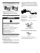
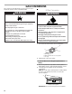
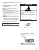
3. Remove plastic cover from gas pressure regulator cap.
4. Turn gas pressure regulator cap counterclockwise with a ⁵⁄₈"
(1.6 cm) combination wrench to remove.
NOTE: Do not remove the spring beneath the cap.
5. Turn over the gas pressure regulator cap and reinstall on
regulator so that the hollow end faces out and the marking
“LP” is facing the direction shown in the above drawing.
6. Replace plastic cover over gas pressure regulator cap.
To Convert Surface Burners (Natural Gas to LP Gas)
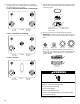
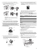
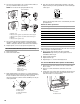
1. Remove burner cap.
2. Remove the burner base.
3. Apply masking tape to the end of a ⁹⁄₃₂" (7 mm) nut driver to
help hold the gas orifice spud in the nut driver while changing
it. Press nut driver down onto the gas orifice spud and
remove by turning it counterclockwise and lifting out. Set gas
orifice spud aside.
4. Remove the orifice spuds shipped in the literature package in
the oven. Gas orifice spuds are stamped with a number,
marked with 1 or 2 color dots, and have a groove in the hex
area. Replace the Natural gas orifice spud with the correct LP
gas orifice spud.
Refer to the following chart for correct LP gas orifice spud
ratings and to spud holder card for proper placement.
LP Gas Orifice Spud Chart for Surface Burners
*Not in all kits/models.
NOTE: Refer to the model/serial/rating plate located on the oven
frame behind the top right-hand side of the oven door for proper
sizing of spuds for each burner location.
5. Place Natural gas orifice spuds in the orifice spud bag.
IMPORTANT: Keep the Natural gas orifice spuds in case of
reinstallation with Natural gas.
6. Replace the burner base.
7. Replace burner cap.
8. Repeat steps 1 to 7 for the remaining burners.
To Convert Oven Bake Burner (Natural Gas to LP Gas)
1. Remove the oven racks and the oven door. See the “Oven
Door” section.
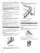
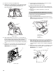
2. Remove 2 screws and washers at the rear of the oven
bottom.
3. Lift the rear of the oven bottom up and back until the front of
the panel is away from the front frame. Remove from oven
and set it aside on a covered surface.
A. Plastic cover
B. Gas pressure regulator cap with solid end facing out
C. Gas pressure regulator cap with hollow end facing out
D. Washer
E. Gas pressure regulator cap
A. Igniter electrode
B. Burner cap
C. Gas tube opening
D. Burner base
A. Igniter electrode
B. Orifice spud
C. Orifice spud holder
D. Screws
A
B
C
D
Side view before
Side view after
E
NG
LP
NG
LP
D
A
B
C
A
B
C
D
A. LP groove
Burner Rating/
Type
Color Size
(mm)
ID
Number
Placement
15,000 BTU/
Stacked*
Silver
Black/Orange
1.05
0.32
L105
L32
LF
14,200 BTU/
Ultra/Stacked*
Silver 1.05 L105 LF/RF
8,000 BTU/
Semi
Red/Orange 0.85 L85 RR/CTR
5,000 BTU/
Auxi
Red/Blue 0.65 L65 LR
1,200 BTU/
Stacked/
Simmer*
Black/Orange 0.32 L32 LF
(Simmer)
A. Screws
B. Oven bottom
A
A
B